


35
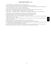
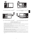
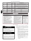
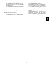
BURNER
ORIFICE
A93059
Fig. 50 -- Orifice Hole
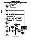
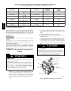
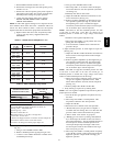
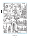
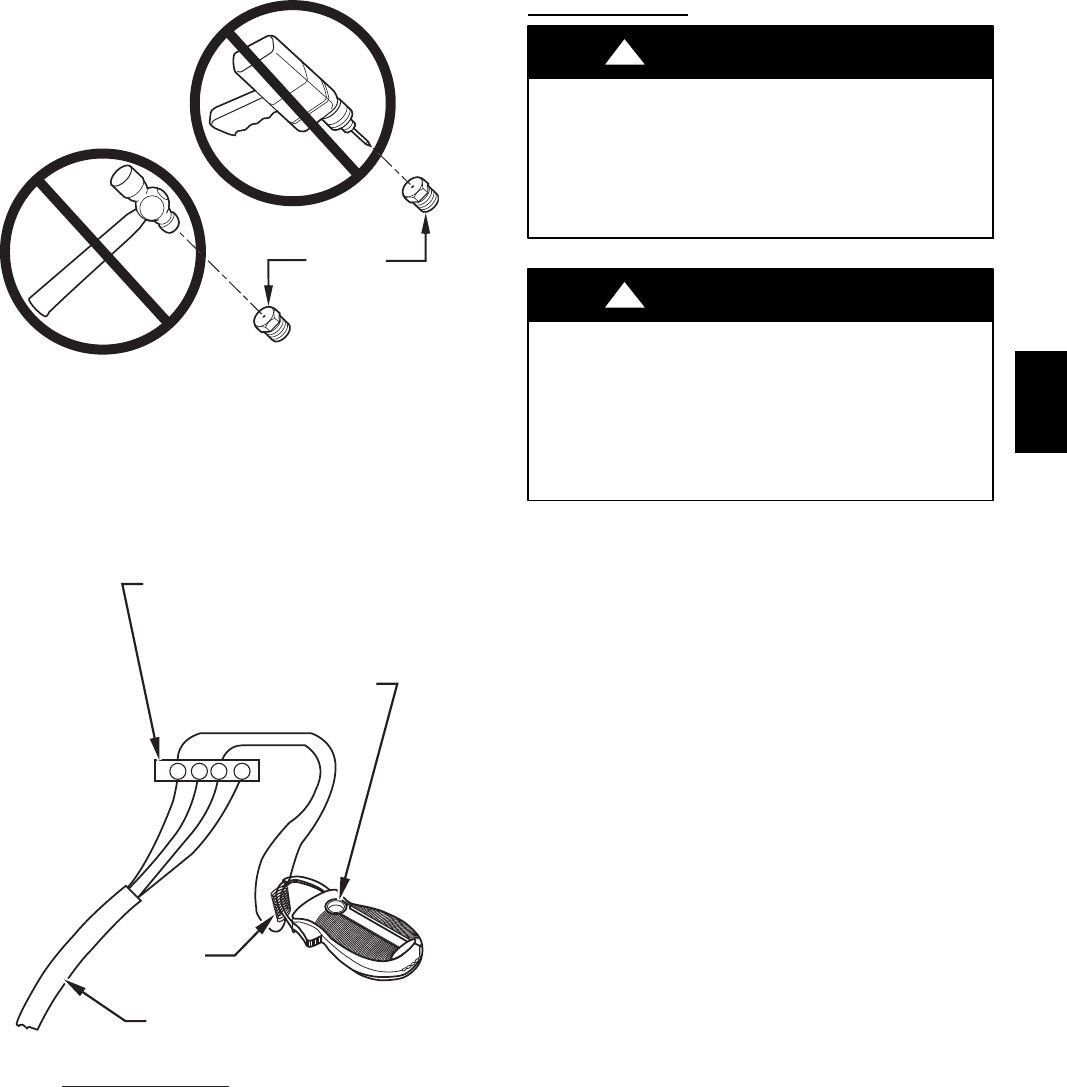
R Y W G
10 TURNS
THERMOSTAT SUBBASE
TERMINALS WITH
THERMOSTAT REMOVED
(ANITICIPATOR, CLOCK, ETC.,
MUST BE OUT OF CIRCUIT.)
HOOK-AROUND
AMMETER
EXAMPLE:
5.0 AMPS ON AMMETER
10 TURNS AROUND JAWS
=
0.5 AMPS FOR THERMOSTAT
ANTICIPATOR SETTING
FROM UNIT 24-V
CONTROL TERMINALS
A96316
Fig. 51 -- Amp. Draw Check with Ammeter
Start--Up Procedur
es
FIRE AND EXPLOSION HAZARD
Failure to follow this warning could cause personal injury,
death or property damage.
Never test for gas leaks with an open flame. Use a
commercially available soap solution made specifically for
detection of leaks to check all connections.
!
WARNING
ELECTRICAL SHOCK HAZARD
Failure to follow this warning could result in personal
injury, or death.
Blower access door switch opens 115--v power to control.
No component operation can occur unless switch is closed.
Caution must be taken when manually closing this switch
for service purposes.
!
WARNING
1. Purge gas lines after all connections have been made.
2. Check gas lines for leaks.
3. To Begin Component Self--Test:
Remove Blower Access Door. Disconnect the thermostat
R lead from furnace control board. Manually close blower
door switch. Turn Setup DIP switch SW1--6 ON. (See Fig.
26, 53 and Table 10.)
NOTE: The furnace control allows all components, except the
gas valve, to be run for short period of time. This feature helps
diagnose a system problem in case of a component failure.
Component test feature will not operate if any thermostat signal is
present at the control.
Refer to service label attached to furnace or See Fig. 52.
Component test sequence is as follows:
a. Inducer motor starts on high--speed and continues to
run until Step d. of component test sequence.
b. Hot surface igniter is energized for 15 sec., then off.
c. Blower motor operates for 15 sec.
d. Inducer motor goes to low--speed for 10 sec., then
stops.
e. After component test is completed, one or more status
codes (11, 25, or 41) will flash. See component test
section of service label (Fig. 52) in furnace for explan-
ation of status codes.
NOTE: To repeat component test, turn setup switch SW1--6
OFF, then back ON.
4. Turn setup DIP switch SW1--6 OFF. Reconnect R lead to
furnace control board, release blower door switch and re-
install blower access door.
5. Operate furnace per instruction on inner door.
6. Verify furnace shut down by lowering thermostat setting
below room temperature.
7. Verify furnace restarts by raising thermostat setting above
room temperature.
315AAV