


53
seconds after the GVR closes, a 2--second flame prov-
ing period begins. The HSI igniter will remain ener-
gized until the flame is sensed or until the 2--second
flame proving period begins. If the furnace control
CPU selects high--heat operation, the high--heat gas
valve solenoid GV--HI is also energized.
d. Flame--Proving -- When the burner flame is proved at
the flame--proving sensor electrode FSE, the inducer
motor IDM switches to low--speed unless the furnace
is operating in high--heat, and the furnace control CPU
begins the blower--ON delay period and continues to
hold the gas valve GV--M open. If the burner flame is
not proved within two seconds, the control CPU will
close the gas valve GV--M, and the control CPU will
repeat the ignition sequence for up to three more Tri-
als--For--Ignition before going to Ignition--Lockout.
Lockout will be reset automatically after three hours,
or by momentarily interrupting 115 vac power to the
furnace, or by interrupting 24 vac power at SEC1 or
SEC2 to the furnace control CPU (not at W/W1, G, R,
etc.). If flame is proved when flame should not be
present, the furnace control CPU will lock out of Gas--
Heating mode and operate the inducer motor IDM on
high speed until flame is no longer proved.
e. Blower--On delay -- If the burner flame is proven the
blower--ON delays for low--heat and high--heat are as
follows:
Low--heat -- 45 seconds after the gas valve GV--M is
opened the blower motor BLWM is turned ON at
low--heat airflow.
High--heat -- 25 seconds after the gas valve GV--M is
opened the BLWM is turned ON at high--heat airflow.
Simultaneously, the humidifier terminal HUM and
electronic air cleaner terminal EAC--1 are energized
and remain energized throughout the heating cycle.
f. Switching from Low-- to High--Heat -- If the furnace
control CPU switches from low--heat to high--heat, the
furnace control CPU will switch the inducer motor
IDM speed from low to high. The high--heat pressure
switch relay HPSR is de--energized to close the NC
contact. When sufficient pressure is available the high--
heat pressure switch HPS closes, and the high--heat gas
valve solenoid GV--HI is energized. The blower motor
BLWM will transition to high--heat airflow five
seconds after the furnace control CPU switches from
low--heat to high--heat.
g. Switching from High-- to Low--Heat --The furnace
control CPU will not switch from high--heat to low--
heat while the thermostat R--to--W circuit is closed
when using a single--stage thermostat.
h. Blower--Off Delay --When the thermostat is satisfied,
the R to W circuit is opened, de--energizing the gas
valve GV--M, stopping gas flow to the burners, and
de--energizing the humidifier terminal HUM. The in-
ducer motor IDM will remain energized for a
5--second post--purge period. The blower motor
BLWM and air cleaner terminal EAC--1 will remain
energized at low--heat airflow or transition to low--heat
airflow for 90, 120, 150, or 180 seconds (depending
on selection at blower--OFF delay switches). The fur-
nace control CPU is factory--set for a 120--second
blower--OFF delay.
2. Two--Stage Thermostat and Two--Stage Heating
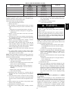
See Fig. 27--34 for thermostat connections.
NOTE: In this mode the low--heat only switch SW1--2 must be
ON to select the low--heat only operation mode in response to
closing the thermostat R--to--W1 circuit. Closing the thermostat
R--to-- W1--and--W2 circuits always causes high--heat operation,
regardless of the setting of the low--heat only switch.
The wall thermostat “calls for heat”, closing the R--to--W1 circuit
for low--heat or closing the R--to--W1--and--W2 circuits for
high--heat. The furnace control performs a self--check, verifies the
low--heat and high--heat pressure switch contacts LPS and HPS
are open, and starts the inducer motor IDM in high--speed.
The start up and shut down functions and delays described in
item 1. above apply to the 2--stage heating mode as well, except
for switching from low-- to high--Heat and vice versa.
a. Switching from Low-- to High--Heat -- If the thermo-
stat R--to--W1 circuit is closed and the R--to--W2 cir-
cuit closes, the furnace control CPU will switch the
inducer motor IDM speed from low to high. The
high--heat pressure switch relay HPSR is de--energized
to close the NC contact. When sufficient pressure is
available the high--heat pressure switch HPS closes,
and the high--heat gas valve solenoid GV--HI is ener-
gized. The blower motor BLWM will transition to
high--heat airflow five seconds after the R--to--W2 cir-
cuit closes.
b. Switching from High-- to Low--Heat --If the thermo-
stat R--to-- W2 circuit opens, and the R--to--W1 circuit
remains closed, the furnace control CPU will switch
the inducer motor IDM speed from high to low. The
high--heat pressure switch relay HPSR is energized to
open the NC contact and de--energize the high--heat
gas valve solenoid GV--HI. When the inducer motor
IDM reduces pressure sufficiently, the high--heat pres-
sure switch HPS will open. The gas valve solenoid
GV--M will remain energized as long as the low--heat
pressure switch LPS remains closed. The blower motor
BLWM will transition to low--heat airflow five
seconds after the R--to--W2 circuit opens.
3. Cooling mode
The thermostat “calls for cooling”.
a. Single--Speed Cooling--
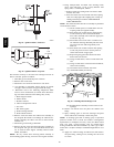
See Fig. 27 for thermostat connections
The thermostat closes the R--to--G--and--Y circuits. The
R--to-- Y circuit starts the outdoor unit, and the R--to--
G--and--Y/Y2 circuits start the furnace blower motor
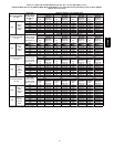
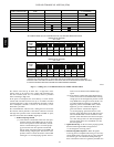
BLWM on cooling airflow. Cooling airflow is based
on the A/C selection shown in Fig. 57. The electronic
air cleaner terminal EAC--1 is energized with 115 vac
when the blower motor BLWM is operating.
When the thermostat is satisfied, the R--to--G--and--Y
circuits are opened. The outdoor unit will stop, and the
furnace blower motor BLWM will continue operating
at cooling airflow for an additional 90 seconds. Jump-
er Y/Y2 to DHUM to reduce the cooling off--delay to
5 seconds. (See Fig. 26.)
b. Single--Stage Thermostat and Two--Speed Cooling
(Adaptive Mode) --
See Fig. 34 for thermostat connections.
This furnace can operate a two--speed cooling unit
with a single--stage thermostat because the furnace
control CPU includes a programmed adaptive se-
quence of controlled operation, which selects low--
cooling or high--cooling operation. This selection is
based upon the stored history of the length of previous
cooling period of the single--stage thermostat.
NOTE: The air conditioning relay disable jumper ACRDJ must
be connected to enable the adaptive cooling mode in response to
a call for cooling. (See Fig. 26.) When ACRDJ is in place the
furnace control CPU can turn on the air conditioning relay ACR
to energize the Y/Y2 terminal and switch the outdoor unit to
high--cooling.
315AAV