


33
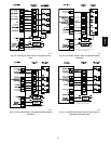
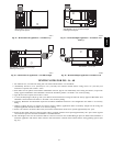
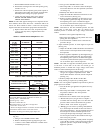
SEE NOTES: 1,2,4,5,7,8,9 on the page
following these figures
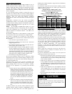
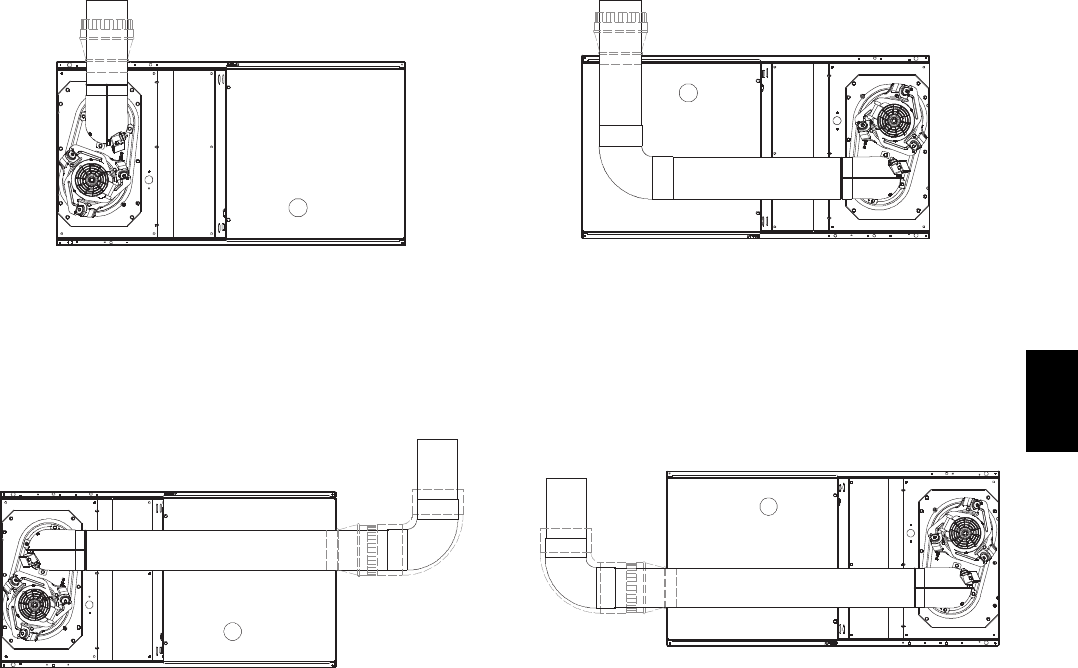
A03215
Fig. 45 -- Horizontal Left Application -- Vent Elbow Up
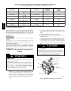
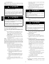
SEE NOTES: 1,2,4,5,7,8,9 on the page
following these figures
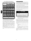
A03216
Fig. 46 -- Horizontal Left Application -- Vent Elbow Right
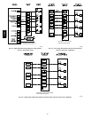
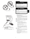
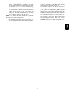
SEE NOTES: 1,2,4,5,7,8,9 on the page
following these figures
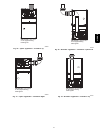
A03219
Fig. 47 -- Horizontal Right Application -- Vent Elbow Left
then Up
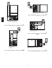
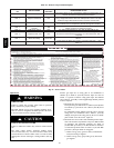
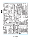
SEE NOTES: 1,2,4,5,7,8,9
A02068
Fig. 48 -- Horizontal Right Application--Vent Elbow Left
VENTING NOTES FOR FIG. 36 -- 48
1. For common vent, vent connector sizing and vent material: United States----use the NFGC.
2. Immediately increase to 5--in. (102 mm) or 6--in. (152 mm) vent connector outside furnace casing when 5--in. (127 mm) vent
connector is required, refer to Note 1 above.
3. Side outlet vent for upflow and downflow installations must use Type B vent immediately after exiting the furnace, except when
factory--approved Downflow Vent Guard Kit is used in the downflow position. See Table 17 for accessory listing.
4. Type--B vent where required, refer to Note 1 above.
5. A 4--in.(102 mm) single--wall (26 ga. min.) vent must be used inside furnace casing and when the factory--approved Downflow Vent
Guard Kit is used external to the furnace. See Table 17 for accessory listing.
6. Accessory Downflow Vent Guard Kit required in downflow installations with lower vent configuration. See Table 17 for accessory
listing.
7. Chimney Adapter Kit may be required for exterior masonry chimney applications. Refer to Chimney Adapter Kit for sizing and
complete application details. See Table 17 for accessory listing.
8. Secure vent connector to furnace elbow with (2) corrosion--resistant sheet metal screws, spaced approximately 180_ apart.
9. Secure all other single wall vent connector joints with (3) corrosion resistant screws spaced approximately 120_ apart. Secure Type--B
vent connectors per vent connector manufacturer’s recommendations.
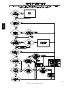
10. The total height of the vent and connector shall be at least seven feet for the 154,000 Btuh gas input rate model when installed in a
downflow application with furnace elbow turned to left side with the connector elbow outside furnace casing pointing upward. (See
Fig. 38.)
315AAV