


30
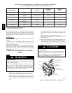
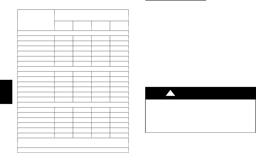
Table 9 – Minimum Allowable Input Rating of
Space--Heating Appliance in Thousands of Btuh per Hour
VENT HEIGHT
FT. (M)
INTERNAL AREA OF CHIMNEY
SQ. IN. (SQ. MM)
12
(7741)
19
(12258)
28
18064)
38
(24516)
Local 99% Winter Design Temperature: 17 to 26 degrees F
6 0 55 99 141
8 52 74 111 154
10 NR 90 125 169
15 NR NR 167 212
20 NR NR 212 258
30 NR NR NR 362
Local 99% Winter Design Temperature: 5 to 16 degrees F*
6 NR 78 121 166
8 NR 94 135 182
10 NR 111 149 198
15 NR NR 193 247
20 NR NR NR 293
30 NR NR NR 377
Local 99% Winter Design Temperature: ---10 to 4 degrees F*
6 NR NR 145 196
8 NR NR 159 213
10 NR NR 175 231
15 NR NR NR 283
20 NR NR NR 333
30 NR NR NR NR
Local 99% Winter Design Temperature: ---11 degrees F or
lower
Not recommended for any vent configuration.
*Th e 99.6% heating (db) temperatures found in the 1997 or 2001
ASHRAE Fundamentals Handbook, Climatic Design Information chapter,
Table 1A (United States) and 2A (C a nada) or the 2005 ASHRAE Funda-
mentals handbook, Climatic Design Information chapter, and the CD---
ROM included with the 2005 ASHRAE Fundamentals Handbook.
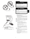
Air for combustion must not be contaminated by halogen
compounds which include chlorides, fluorides, bromides, and
iodides. These compounds are found in many common home
products such as detergent, paint, glue, aerosol spray, bleach,
cleaning solvent, salt, and air freshener, and can cause corrosion
of furnaces and vents. Avoid using such products in the
combustion--air supply. Furnace use during construction of the
building could cause the furnace to be exposed to halogen
compounds, causing premature failure of the furnace or venting
system due to corrosion.
Vent dampers on any appliance connected to the common vent
can cause condensation and corrosion in the venting system. Do
not use vent dampers on appliances common vented with this
furnace.
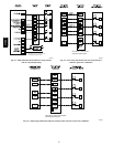
Additional Venting Requir
ements
A 4--in. (102 mm) round vent elbow is supplied with the furnace.
A 5--in. (127 mm) or 6-- in. (152 mm) vent connector may be
required for some model furnaces. A field--supplied 4--in. (102
mm) to 5--in. (127 mm) or 4--in. (102 mm) to 6--in. (152 mm)
sheet metal increaser fitting is required when 5--in. (127 mm) or
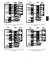
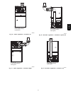
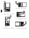
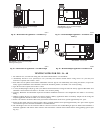
6--in. (152 mm) vent connector is used. See Fig. 36 -- 48, Venting
Orientation for approved vent configurations.
NOTE: Vent connector length for connector sizing starts at
furnace vent elbow. The 4--in. (102 mm) vent elbow is shipped
for upflow configuration and may be rotated for other positions.
Remove the three screws that secure vent elbow to furnace, rotate
furnace vent elbow to position desired, reinstall screws. The
factory--supplied vent elbow does NOT count as part of the
number of vent connector elbows.
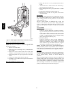
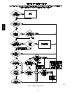
The vent connector can exit the furnace through one of five
locations on the casing.
CUT HAZARD
Failure to follow this caution may result in personal injury.
Sheet metal parts may have sharp edges or burrs. Use care
and wear appropriate protective clothing, safety glasses and
gloves when handling parts, and servicing furnaces.
CAUTION
!
1. Attach the single wall vent connector to the furnace vent
elbow, and fasten the vent connector to the vent elbow
with at least two field--supplied, corrosion--resistant, sheet
metal screws located 180_ apart.
NOTE: An accessory flue extension is available to extend from
the furnace elbow to outside the furnace casing. See Table 17 for
accessory listing. If flue extension is used, fasten the flue
extension to the vent elbow with at least two field--supplied,
corrosion--resistant, sheet metal screws located 180_ apart. Fasten
the vent connector to the flue extension with at least two
field--supplied, corrosion resistant sheet metal screws located
180_ apart.
2. Vent the furnace with the appropriate connector as shown
in Fig. 36 -- 48.
3. Determine the correct location of the knockout to be re-
moved.
4. Use a hammer and screwdriver to strike a sharp blow
between the tie points and work the slug back and forth
until the slug breaks free.
An accessory Vent Guard Kit is REQUIRED for downflow
applications for use where the vent exits through the lower
portion of the furnace casing. Refer to the Vent Guard Kit
Instructions for complete details. See Table 17 for accessory
listing.
315AAV