


Date: 8-4-2010
Revision: 0
Form: 2396
BE REMOVED after the boiler is set in-place on
its concrete foundation before any
piping/electrical connections are made. It is
recommended that the plastic protective cover
be left on as long as possible to reduce finish
damage from the installation.
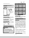
1.4 BOILER CONNECTIONS
Do not run any pipes along the tube access
panel side of the boiler. Maintain clearances as
shown on the dimensional drawing for servicing
of the boiler tubes. Provide at least 48" from the
front of the boiler, unless a larger dimension is
indicated on the dimensional. All piping should
be designed and installed to avoid any loadings
on the boiler connections or piping.
1.4.1 FLOW CONNECTION
The system supply and return flow connections
are shown on Figure 3 and Figure 4
respectively. A gate valve should be installed on
the boiler outlet and inlet lines. This allows the
boiler to be isolated from the heating system for
draining and servicing.
1.4.2 SAFETY RELIEF VALVES
Safety relief valve(s) are shipped loose.
Connections are provided in the top of the boiler
for the safety relief valve(s). The safety relief
valve discharge piping must be the same size as
the safety relief valve discharge opening and run
to a point of safe discharge. Avoid over-
tightening as this can distort valve seats. All
piping from the safety relief valve(s) must be
independently supported with no weight carried
by the valve.
1.4.3 EXPANSION TANK
CONNECTIONS
Connection(s) to an expansion tank are to be
provided by others in the system piping separate
from the boiler.
1.4.4 DRAIN CONNECTION
A drain valve must be installed on the boiler
drain connection, the same pipe size as this
connection, to allow draining of the boiler.
1.4.5 CONDENSATE DRAIN
CONNECTION
A 1” MPT connection is provided to drain the
condensed products of combustion from a trap
located beneath the boiler. This must be run to
a drain using stainless steel or PVC piping. The
condensate temperature should never exceed
212
o
F and the pH of the condensate should
never be greater than 3.5. NO VALVE is to be
installed in this line from the boiler to point of
discharge.
1.4.6 GAS SUPPLY CONNECTION
The installation must conform completely to the
requirements of the authority having jurisdiction,
or in the absence of such, requirements shall
conform in the U.S. to the current National Fuel
Gas Code, ANSI Z223.1-1984, or in Canada to
the current Natural gas and propane installation
code (CAN/CSA B149.1-05), and applicable
regional regulations for the class; which should
be followed carefully in all cases. Authorities
having jurisdiction should be consulted before
installations are made.
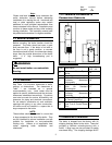
1.4.7 DRIP LEG
A drip leg, or sediment trap, must be installed in
the gas supply line. See Fig. 1.5A. The gas line
must be connected to a supply main at least as
large as the gas train connection at the boiler.
This connection should be made with a union so
that the boiler gas train components and burner
may be easily removed for service.
1.4.8 GAS PIPING LEAK TEST
Leaks shall be checked using a soap and water
solution.
3
After completion of the gas-piping hookup, the
installation must be checked for leaks. All joints
up to the main motorized gas valve shall be
checked. A pressure gauge shall be installed
down stream of the main motorized gas valve
and up stream of the manual gas shutoff valve in
the closed position to ensure the main motorized
valves are not leaking by. During
commissioning, the remainder of the gas train
joints down stream of the main motorized gas