


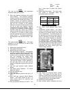
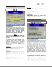

Date: 8-4-2010
Revision: 0
Form: 2396
NOTE:
The low fire displacement final adjustment
should be made at low fire only.
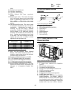
3. Main gas pressure regulating and shutoff
valve actuator. The pressure regulating
actuator provides slow opening fast closing
safety shutoff and air/gas ratio control. The
actuator controls the pressure difference
across the gas limiting orifice valve (Figure 7
item 26) as a function of the pressure
difference across the furnace section so that
the air to gas ratio remains constant
irrespective of air volume changes. There is
no need for an upstream constant pressure
regulator when the supply gas pressure
does not exceed 56 inches of water column.
A minimum of 14 inches of water column
must be supplied at the gas inlet connection
(Figure 6 item 1). The supply pressure can
be measured at the test port (Figure 7 item
28).
NOTE:
The supply pressure is not static. The supply
pressure is at the maximum full flow of gas
through the burner.
4. Manual main gas shutoff valve.
5. Pilot ignition transformer.
6. Manual pilot gas shutoff valve.
7. Pilot gas pressure regulator. This regulator
provides a constant gas pressure to the pilot
when the solenoid valve is energized. The
pressure can be adjusted by removing the
cap and adjusting the slotted screw
clockwise to increase the pressure and
counter-clockwise to decrease the pressure.
The pilot gas supply is taken upstream of
the main gas cock so the pilot may be
lighted and adjusted with the main gas cock
closed.
8. Low pilot gas pressure switch (Manual
Reset)
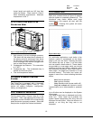
9. Pilot spark igniter assembly. For further
detail see Figure 9.
10. Pilot gas solenoid valve.
11. Flame scanner.
12. Main gas manifold pressure test port (1/4”
NPT).
13. Main high gas pressure switch (Manual
Reset). This switch should be set 1” of
water column above the maximum gas
manifold pressure.
14. Pilot gas pressure test port (1/4” NPT). This
port is also used to record the furnace
pressure.
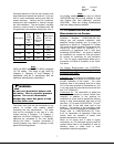
15. Boiler water flow switch. The boiler water
flow switch is adjustable within the
parameters listed in the table.
Mode Of Operation
Settings
Switch
Closed
Switch
Open
Minimum 30 gpm 12 gpm
Maximum 52.1
gpm
46.1
gpm
Table 4 Water Flow Switch Settings
16. Low Water Cutoff (Manual Reset Probe
Type).
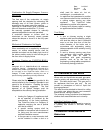
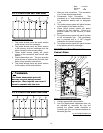
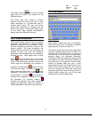
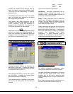
17. Combustion air-flow switch. An airflow
switch is provided to prove that air is being
provided to the burners before main flame
can be established. The airflow switch can
be adjusted by turning the screw (Figure 8
item A) clockwise to increase the pressure
setting and counter-clockwise to decrease
the pressure setting. The switch will open
on pressure drop. When the blower is
running there should be continuity between
the common and the normally open contacts
(Figure 8 item B and C). When the blower is
interrupted the switch should open and
cause a safety shutdown.
A
B
C
Figure 8 Air Flow Switch
18. High burner air pressure switch manual
reset. This switch will trip when the air
pressure in the burner rises above the set-
point, indicating that the burner has become
plugged with dust or other foreign matter.
19. Gas and air mixer assembly.
14
20. Main 3-phase power connection and fuse