


Date: 8-4-2010
Revision: 0
Form: 2396
2.3 BOILER COMMISSIONING
NOTE:
All of the installation instructions found in section
1 must be completed before commissioning the
boiler.
WARNING:
The following procedures must be
followed carefully before putting the
boiler in operation. Failure to do so
will present severe hazards to
equipment, operating personnel and
building occupants.
2.3.1 MODULATION
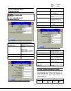
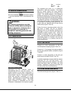
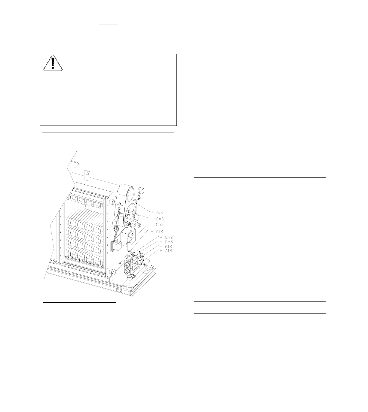
Figure 39 Air / Gas Ratio Tappings
Modulation on the Triple-flex boiler is
accomplished with air / gas ratio control. The
system consists of two major components, a
blower (Figure 10 item 6) and a regulating gas
valve (Figure 7 item 3). The blower is variable
speed and provides combustion air to the
burner. The blower rpm is controlled by a PWM
(pulse width modulation) signal. The PWM
signal increases or decreases as the load
increases or decreases in the hydronic system.
The regulating gas valve is a 1:1 differential
pressure air / gas ratio controller. This means
that the control adjusts the same pressure
difference on the gas side as it senses on the
airside. The airside pressure is the difference
between the pressure in the burner housing and
the pressure downstream of the furnace section.
The gas side pressure is the difference between
the pressure upstream and downstream of the
gas limiting orifice valve. For the locations of the
+/- gas and air connections see (Figure 39). Air
to gas ratios are adjusted with the gas limiting
orifice valve (Figure 7 item 26).
During the burner pre-purge period, when the
gas valve is closed, only the air pressure
difference acts on the regulator causing the air
diaphragm to move to the left and closes the
regulating hydraulic bypass valve. When the
actuator is powered, the gas valve begins to
open. The downstream gas pressure difference
immediately begins to increase until the gas
pressure difference is in balance with the air
pressure difference.
2.3.2 TEST SETUP
Connect a u-tube manometer to the gas
manifold pressure tapping (Figure 7 item 12).
Connect a 0 – 5 psi gauge in the port provided in
the low gas pressure switch connection (Figure
7 item 28).
Connect a u-tube manometer to the pilot gas
pressure port provided (Figure 7 item 14).
A suitable combustion analyzer shall be used for
measuring O2, CO, and Nox levels. The
analyzer probe should be inserted in the stack
above the boiler outlet and before any draft
controls. Calibration is required for the Nox and
CO cells at the time of commissioning.
2.3.3 PRE CHECKS AND SETUP
Close the manual gas cock (Figure 7 item 4).
35