Date: 8-4-2010
Revision: 0
Form: 2396
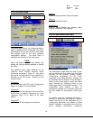
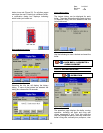
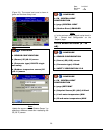
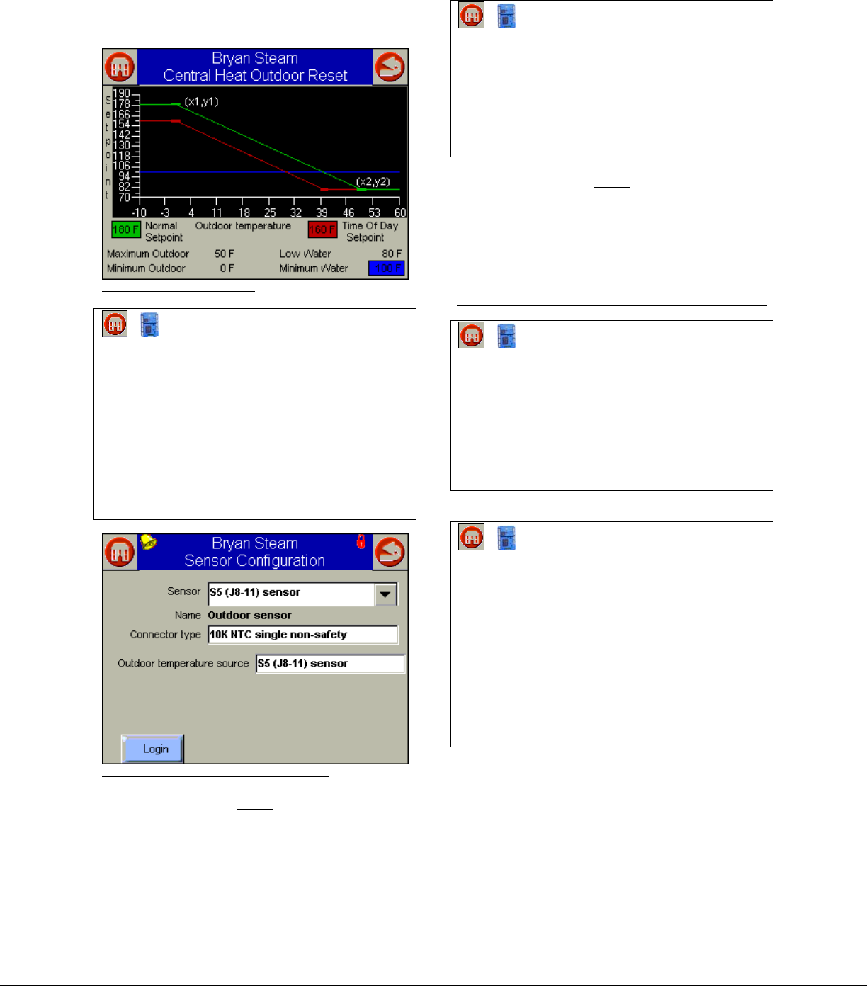
(Figure 34). The normal reset curve is shown in
green and the time of day is red.
Figure 34 Outdoor Reset Curve
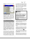
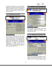
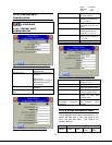
► ► CONFIGURE
► SENSOR CONFIGURATION
► (Sensor) S5 (J8-11) sensor
► (Connector type) 10K NTC single
non-safety
► (Outdoor temperature source) S5
(J8-11) sensor
Figure 35 Outdoor Reset Sensor Configuration
Note:
Update the sensor name to ‘Outdoor Sensor’ by
selecting a different sensor then reselecting the
S5 (J8-11) sensor.
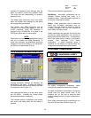
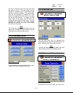
► ► CONFIGURE
► CH - CENTRAL HEAT
CONFIGURATION
► (page) CENTRAL HEAT
► (Outdoor Reset) ENABLED
Note:
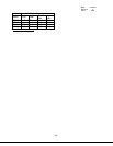
y1 is the maximum water setpoint value found in
‘CH – Central heat Configuration’ on the
‘Setpoint’ page.
2.2.20 REMOTE SETPOINT (4 – 20
MA)
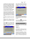
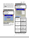
► ► CONFIGURE
► SENSOR CONFIGURATION
► (Sensor) S2 (J8-6) sensor
► (Connector type) 4-20mA
► SAFETY VERIFICATION 2.2.9
► ► CONFIGURE
► CH - CENTRAL HEAT
CONFIGURATION
► (page) SETPOINT
► (Setpoint Source) S2 (J8-6) 4-20mA
► (4 mA water temperature) MIN
► (20 mA water temperature) MAX
26


