


Date: 8-4-2010
Revision: 0
Form: 2396
Actual length and width are 3⁄8” less than
trade size shown. Filters meet UL Class 2
flame retardance requirements. Maximum
temperature is 180° F.
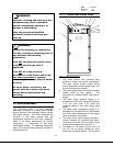
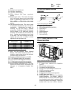
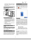
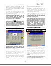
2.1.8 TRIPLE-FLEX RIGHT FLUE
COLLECTOR VIEW
Figure 11 Triple-Flex Right Flue Collector View
1. High primary air-to-air exchanger pressure.
This switch will trip when the air pressure in
the primary air-to-air exchanger rises above
the set-point, indicating that the primary air-
to-air exchanger has become plugged with
dust or other foreign matter.
2. Condensate trap cleanout. This connection
is ½” NPT.
3. Condensate trap. The condensate trap is
welded and fixed into place.
4. Flue vent temperature sensor.
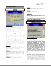
2.2 SOLA HYDRONIC CONTROL
SYSTEM
The Triple-Flex is equipped with a Honeywell
SOLA control system (Figure 3 item 5). This
section will explain navigation, configuration,
history, and diagnostics.
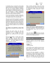
2.2.1 POWER-UP VALIDATION
Flip the power button, (Figure 3 item 6), to the
on position. After a few seconds the Home page
will appear and the POWER LED will be blinking
when the device is properly powered. Select the
Setup button to adjust the contrast as desired.
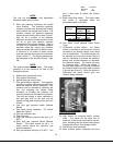
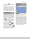
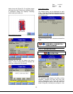
2.2.2 HOME PAGE
Make sure a screen similar to Figure 12 appears
after the system is completely powered up. The
directional map shown before each page
description in this manual will start with this
symbol
. Pressing this symbol will return
you to the home page.
Figure 12 Home Page
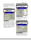
On multi-boiler applications, each boiler in the
hydronic system is represented on the Home
page by an icon and name. Pressing the boiler
icon allows the user to zoom in on that boiler
and see specific details about it. These details
are provided on a new page, which can include
additional buttons that display additional detail
and operation information, which itself leads to
other pages. The pages are traversed in a tree
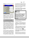
structure method. The boiler icon button will
appear in one of four colors indicating the boiler
status.
• Blue: Normal operation
• Red:
Lockout condition
• Gray:
Standby mode (burner switch off)
• Gray and crossed out: Hydronic control
communication error (disconnected or powered
off)
Up to 8 boilers can be displayed on the System
Home page.
The name of each boiler is displayed next to the
boiler icon. When Lead Lag is enabled, the
system header temperature and firing rate are
displayed for each boiler. When the burner is in
standby or not firing the firing rate is not
displayed.
16