


Date: 8-4-2010
Revision: 0
Form: 2396
the touch panel display. There is a soft
switch (paragraph 2.2.11) provided with the
SOLA hydronic control that will put the boiler
into standby for an indefinite period of time.
WARNING:
The boiler on / off switch will not turn
off the 3 phase high voltage power to
the motor.
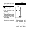
7. The boiler lockout reset button is a push
button used to reset the hydronic control
after a boiler failure.
8. The power on light will be white in color and
indicates that there is 120 volts ac being
supplied to electrically connected devices.
9. The enabled light will be green in color and
indicates that the boiler is enabled. Enabled
is a state in which the boiler is allowed to
operate within the boiler’s predefined
parameters.
10. The fuel on light will be amber in color and
indicates that the boiler is firing and
producing heated water.
11. The boiler lockout light will be red in color
and indicates that the boiler has failed. The
SOLA control will have additional
information displayed on the touch panel
display. These failures will be explained in
section 2.3.9.
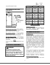
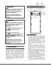
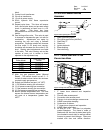
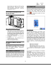
2.1.2 TRIPLE-FLEX REAR VIEW
Figure 4 Triple-Flex Rear View
1. The flue gas vent is 8” diameter and
exhausts products of combustion. Refer to
section 1.7 for installation details.
2. The rear jacket access panel provides
access to the combustion air blower for
servicing.
3. The boiler return water connection receives
cooled water from the system. This
connection is a standard ANSI 150# class 3”
flange.
12
4. The drain connection is 1” NPT and provides
a means for draining water from the boiler.
For installation details refer to paragraph
1.4.4.