


Date: 8-4-2010
Revision: 0
Form: 2396
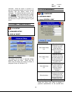
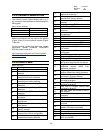
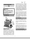
2.2.23 MODBUS COMMUNICATION
The hydronic control Global Modbus port is a 3-
pin connector that interfaces to the following RS-
485 signals:
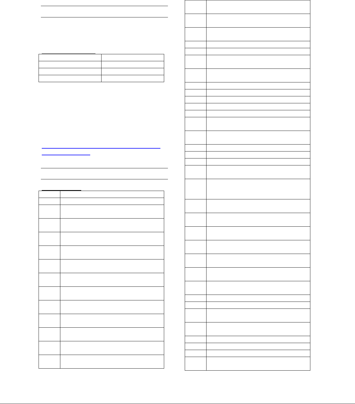
Table 7 Modbus Terminals
Signal Terminal
Data + a
Data - b
Common c
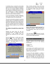
Modbus connections can be made at the display
(Figure 3 item 5) or the hydronic control (Figure
7 item 24).
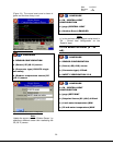
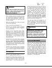
For the modbus register map and other related
information please download Honeywell’s
R7910A product manual at:
http://customer.honeywell.com/TechLit/pdf/66-
0000s/66-1171.pdf
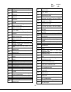
2.2.24 ALERT CODES
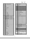
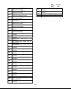
Table 8 Alert Codes
29
Code Description
0 None (No alert)
1
Alert PCB was restored from factory
defaults
2
Safety configuration parameters were
restored from factory defaults
3
Configuration parameters were
restored from factory defaults
4
Invalid Factory Invisibility PCB was
detected
5
Invalid Factory Range PCB was
detected
6
Invalid range PCB record has been
dropped
7
EEPROM lockout history was
initialized
8
Switched application annunciation
data blocks
9
Switched application configuration
data blocks
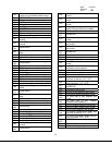
10
Configuration was restored from
factory defaults
11
Backup configuration settings was
restored from active configuration
12
Annunciation configuration was
restored from factory defaults
13
Annunciation configuration was
restored from backup
14
Safety group verification table was
restored from factory defaults
15
Safety group verification table was
updated
16 Invalid Parameter PCB was detected
17 Invalid Range PCB was detected
18
Alarm silence time exceeded
maximum
19
Invalid safety group verification table
was detected
20-26 RESERVED
27 Safety processor was reset
28 Application processor was reset
29 Burner switch was turned OFF
30 Burner switch was turned ON
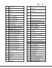
31
Program Module (PM) was inserted
into socket
32
Program Module (PM) was removed
from socket
33 Alert PCB was configured
34 Parameter PCB was configured
35 Range PCB was configured
36
Program Module (PM) incompatible
with product was inserted into socket
37
Program Module application
parameter revision differs from
application processor
38
Program Module safety parameter
revision differs from safety processor
39
PCB incompatible with product
contained in Program Module
40
Parameter PCB in Program Module is
too large for product
41
Range PCB in Program Module was
too large for product
42
Alert PCB in Program Module was
too large for product
43
IAS start check was forced on due to
IAS enabled
44
Low voltage was detected in safety
processor
45 High line frequency occurred
46 Low line frequency occurred
47
Invalid subsystem reset request
occurred
48
Write large enumerated Modbus
register value was not allowed
49 Maximum cycle count was reached
50 Maximum hours count was reached
51 Illegal Modbus write was attempted
52
Modbus write attempt was rejected
(NOT ALLOWED)