


Date: 8-4-2010
Revision: 0
Form: 2396
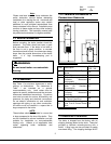
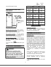
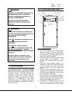
Horizontal sections of the flue vent system must
be pitched back towards the boiler at ¼ inch per
foot to avoid condensate pooling and allow for
proper drainage. Venting may be horizontal,
through the wall installation or vertical, through
the roof installation. The vent system, including
terminus, must be sized in accordance with the
flue gas flow(s) and pressure drop(s) per
Table 3.
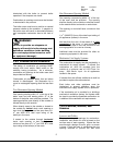
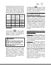
Boiler Model
Flue Gas
Flow,
ACFM
@40%X
SA
200
o
F
Comb Air
Req.
SCFM
@40%XS
A60
o
F
Permissible
∆P Thru
Venting
TF-150 452 330
0.2” WC
(Max)
TF-200 603 441
0.2” WC
(Max)
TF-250 753 550
0.2” WC
(Max)
TF-300 904 661
0.2” WC
(Max)
Table 3 Boiler Draft
Note:
NFPA 54-2009 (ANSI Z223.1-2009) paragraph
12.7.3.3 states, “The sizing of gas vents for
Category II, Category III, and Category IV
Appliances shall be in accordance with the
appliance manufacturers instructions.”
WARNING:
Do not use a barometric damper with
this boiler. This is a positive pressure
system. The use of a barometric
damper may cause flue gases to leak
into the boiler room.
The boiler vent must not be connected to any
portion of another vent system without
consulting the vent manufacturer. The boiler
shall not be connected to any part of a vent
system serving a Category I or Category II
appliance, nor shall a Category I or Category II
appliance be connected to the vent system
serving this boiler. Improper connection of
venting systems may result in leakage of flue
gases into building spaces.
Note:
An existing masonry chimney may be utilized
PROVIDING that the existing chimney is lined
with Special Gas Vent material(s), primarily
AL29-4C®. There are venting manufacturers
that have these products available.
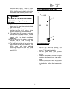
1.7.2 COMBUSTION AIR AND VENTING
REQUIREMENTS FOR CANADA
Canadian Standard CAN/CSA-B149.1-05,
Natural gas and propane installation code
specifies venting systems and air supply for
appliances in Section 8. Paragraph 8.1.4 states
“Air supply shall be provided in accordance with
Clause 8.4 when either an appliance or a
combination of appliances has a total input
exceeding 400,000 Btuh”. Air supply is defined
as combustion air, excess air, flue gas dilution
air, primary air, secondary air, and ventilation
air. The air supply requirements below are a
summation of Clause 8.4 specific to the Triple-
Flex boiler.
Air Supply Requirements per CAN/CSA-
B149.1-05 for Appliances having an input
exceeding 400 MBH.
Ventilation Air: an opening for ventilation air at
the highest point that opens to the outdoors shall
provide Ventilation of the space. The cross
sectional area of this opening shall be at least
10% of the area required for combustion air, but
in no case shall the cross-sectional area be less
that 10 in
2
(6500mm
2
).
Combustion Air: For combustion air where the
air supply is provided by natural airflow from
outdoors, in addition to the opening for
ventilation air, there shall be permanent opening
having a total cross-sectional free area of not
less than 1 in
2
for each 30,000 BTU/hr. (70 mm
2
for each kW) of the total rated input of the
boiler(s). The location of the opening(s) shall
not interfere with the openings for ventilation air.
Please refer to CAN/CSA-B149.1-05, Para.
8.4.4, for combustion air openings if there are
natural draft, fan assisted or power draft
assisted equipment in the space.
When an air supply duct is used to supply
combustion air, it’s discharge opening shall be
located where there is no possibility of cold air
affecting steam or water lines or other
temperature sensitive equipment.
7