


Date: 8-4-2010
Revision: 0
Form: 2396
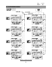
4.4 LEAD-LAG OPERATION
This is a summary of the functional capability of
the embedded lead-lag on the Sola control.
OEM Configurable parameters may be adjusted
as part of the OEM factory configuration and in
the field using the System Display with
appropriate password permissions. Specific
parameters may also be configured in the field
by the local display 1. Field Installation
Configuration a. The master and slave
controllers are enabled via the S7910 or S7999
display. b. All Sola controllers are programmed
with a default address of 1. Assuming the
Master Sola controller remains address 1, the
address of the slave controllers in the system
must have a unique address (1..8) via the local
display. 2. Basic Operation a. Firing rate
determination – Parallel common-base limited
(1) All boilers have a single assignable base
load firing rate. (2) Allocation (a)As load
increases: (i) Until all stages are Firing - No
stage is requested to exceed the common base
load rate. (ii)After all stages are Firing - There is
no restriction on the slave's commanded firing
rate. (b)As load decreases: (i) As long as all
available stages are firing - There is no
restriction on the slave's commanded firing rate.
(ii)When at least one stage has been dropped -
No stage is requested to exceed the common
base load rate. b. Rotation (1) The lead boiler is
rotated based sequence order. The lead boiler
rotation time is a configurable OEM assigned
parameter. Rotation is sequential by address (1-
2-3-4; 2-3-4-1; etc.) (2) Rotation trigger occurs at
the start of each new heat cycle. c. Source of
heat for call – The call for heat originates at the
master boiler. This source may be configured to
be an external thermostat or via EnviraCOM
Remote Stat. d. Slave boiler lockout – If any
slave is in lockout the master boiler will cause it
to be skipped and all system load setting
calculation settings will be based only on
available boilers. e. Master boiler lockout – If the
master boiler is in lockout then its burner control
function will be skipped in the rotation the same
as the slave controllers. However, the master
boiler function will continue to operate. 3.
System Component Failure Responses a. If the
system header sensor becomes disconnected
from the master boiler then the master boiler will
control off of one of the following OEM
configurable actions (1) Disable - No backup will
be used (a)Lead Outlet - Outlet temperature of
the lead boiler will be used as the backup during
firing (i) Slave Outlet Average - Average of the
outlet temperatures of all slave boilers that are
firing will be used as a backup (b) If the sensor
chosen by the above parameter is faulty then
the backup sensor provided may be used. When
burner demand is off and no burners are firing
then, for either "Lead Outlet" or "Slave Outlet
Average", the lead boiler's outlet temperature is
used to monitor for burner demand. 4. Local
Display Configuration and Operation a. The
configuration parameters available on the local
display are edited in the Service Mode b. Access
to the Service Mode is accomplished by
pressing both up/down buttons for 3 seconds. c.
Status and Operation (1) Slave status (a) “Rmt”
and “Adr” icons are on to show slave (follower)
has been enabled. (b)Current burner status is
shown (c) To show slave CFH (i) Alternate “%”
firing rate and actual (slave) Outlet temp to
indicate slave CFH otherwise show the Home
screen. (2) Master status (a)Rmt icon is on, Adr
icon is off to show Master (Leader) has been
enabled. (b)Current burner status is shown (c)
Actual temperature LL (Header) temperature is
shown as described in 4e below. (d)Pressing the
up/down buttons allows setpoint adjustment for
LL-CH only (not LL-DHW or LL-Mix or others). (i)
All pump configurations must be done using the
PC Configuration tool in the OEM factories.
(e)To show Master CFH (i) Alternate “CH” or
“LL” or “Hdr” in numbers field with the actual
temperature to indicate LL CH CFH. d.
Configuration (1) Continue scrolling through set-
up screens until “Remote Firing Control” screen
is reached. (2) Rmt On/Off selection chooses to
navigate the user through the Master/Slave
configuration as existing today (3) Set
master/slave remote address as is done on
currently on the local display. (4) The following
parameters are mapped to Modbus addresses.
LEAD LAG
5 66—A1171 (a) “LL” = LL Operation (3
user selections available) (i) “Ldr” (i-a)Master
Enable (i-b)Slave Enable (ii)“SLA” (ii-a)Slave
Only Enable (ii-b)Master Disable (i) “OFF” (iii-
a)Master Disable (iii-b)Slave Disable (b)HS =
On/Off Hysteresis (One value used for all LL
boilers) (i) “HS” for on and off hysteresis values.
(i-a)Only allow 1 setting for both on and off
hysteresis values. (a-1)Must adhere to the
strictest of either the HS On or Off limits. •
Highest value of the “low” range limit in Sola
control • Lowest value of the “high” range limit in
Sola control (a-2)See Sola Modbus specification
for details. • Typical values: 2-15 (c) BL =
59