


Date: 8-4-2010
Revision: 0
Form: 2396
block.
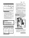
21. Control circuit transformer.
22. 24 volt ac transformer.
23. 12 volt dc power supply.
24. SOLA hydronic and flame supervision
control.
25. Repeat cycle timer. This timer will ensure
that a forced shut down and pre-start safety
check is performed at least once in a 24
hour period. This timer has been
incorporated into the SOLA control for newer
boilers.
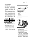
26. Gas limiting orifice valve. This valve is used
to increase or decrease the gas / air ratio for
combustion. Adjustments are made by
removing the cap and using a flathead
screwdriver. Clockwise rotation will increase
the flue outlet % O2 levels and counter-
clockwise will decrease the flue outlet % O2
level. Starting point adjustments are listed
in the table. This vale is factory set and the
number of turns out is written in black
adjacent to the adjustment cap.
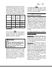
Boiler Model
Turns Out From
Bottom
TF300 8-1/2 to 9
TF250 8-1/2 to 9
TF200 6-1/2 to 7
TF150 6-1/2 to 7
Table 5 Gas Limiting Orifice Rough Settings
27. Main low gas pressure switch (Manual
Reset). This switch should be set 2 – 3
inches of water column below the minimum
required supply gas pressure.
28. Supply gas pressure test port (1/4” NPT).
29. (-) Air pressure sensing line connection.
30. (+) Air pressure sensing line connection.
31. (-) Gas pressure sensing line connection.
32. (+) Gas pressure sensing line connection.
33. Burner internal temperature fuse. This fuse
senses the internal burner temperature and
will open at a temperature greater than
425
o
F.
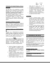
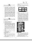
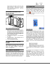
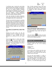
2.1.6 PILOT SPARK IGNITER
ASSEMBLY
Figure 9 Pilot Spark Igniter Assembly
1. Spark grounding screw.
2. Pilot igniter gas orifice (#49 Drill)
3. Shell body ¾”.
4. Gland nut.
5. Igniter electrode.
6. Brass bushing.
7. Gas inlet fitting.
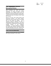
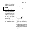
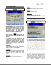
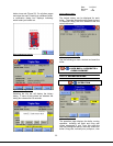
2.1.7 TRIPLE-FLEX LEFT FLUE
COLLECTOR VIEW
Figure 10 Triple-Flex Left Flue Collector View
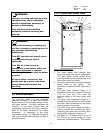
1. 3” Lower drum cleanout and inspection
opening.
2. Furnace tube access panel.
3. Convection tube access panel.
4. Primary air-to-air exchanger access cover.
5. ASME name-plate stamping.
6. Combustion air blower.
7. 3” Upper drum cleanout and inspection.
8. ASME Safety relief valve.
15
9. Air filter 20” x 25”. This filter is a polyester
coated fiberglass. The frame is made of
fiberboard and has two tin-plated steel grills
(one bonded to each side) as well as sealed
corners to prevent dust leakage. Filters are
marked with size and airflow direction.