


Date: 8-4-2010
Revision: 0
Form: 2396
There are parameters that are available to set
the features for Lead Lag.
Many of the descriptions used are internal
functions or tables. The names help define the
functions but are not controlled or selectable
outside Sola, unless noted as a parameter.
4.1 GENERAL DESCRIPTION OF THE
LEAD LAG APPLICATION
Sola devices contain the ability to be a stand
alone control, operate as a Lead Lag Master
control which also uses the Sola control function
as one of the slaves or to operate solely as a
slave to the lead lag system. Conceptually it is
not a part of that specific control, but is an entity
that is "above" all of the individual Sola controls
(including the one that hosts it). The master
sees each slave (including the one that hosts it)
as a set of Modbus devices, each having certain
registers, and in this regard it is entirely a
communications bus device, talking to the slave
Sola controls via Modbus.
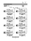
Sola devices utilize two ‘ModBus™’ ports (MB1
and MB2) for communications. One port will be
designated to support a system S7999B display
and the other port will support communications
from the LL Master with its slaves. The diagram
on page 4 shows a simplified wiring diagram
connecting the system display with a 4 system
Lead Lag arrangement.
The Lead Lag master is a software service that
is hosted by a Sola control.
The LL master uses a few of the host Sola's
sensors (header temperature and outdoor
temperature) and also the STAT electrical inputs
in a configurable way, to provide control
information.
4.2 LEAD LAG (LL) MASTER GENERAL
OPERATION
The LL master coordinates the firing of its slave
Solas. To do this it must add stages and drop
them to meet changes in load, and it sends firing
rate commands to those that are firing.
The LL master turns the first stage on and
eventually turns the last stage off using the
same criteria as for any modulation control loop.
When the operating point reaches the Setpoint
minus the On hysteresis, then the first Sola is
turned on. When the operating point reaches
the Setpoint plus the Off hysteresis then the last
slave Sola (or all slave Solas) are turned off.
The LL master PID operates using a percent
rate that is, 0% is a request for no heat at all,
and 100% means firing at the maximum
modulation rate.
This firing rate sent to the slaves as a
percentage, but this is apportioned to the slave
Solas according to the rate allocation algorithm
selected by the Rate allocation method
parameter.
For some algorithms this rate might be common
to all slave Solas that are firing. For others it
might represent the total system capacity and be
allocated proportionally.
For example, if there are 4 slaves and the LL
master's percent rate is 30%, then it might
satisfy this by firing all four slaves at 30%,
Or
by operating the first slave at 80% (20% of the
system’s capacity) and a second slave at 40%
(10% of the system’s capacity).
The LL master may be aware of slave Sola’s
minimum firing rate and use this information for
some of its algorithms, but when apportioning
rate it may also assign rates that are less than
this. In fact the add-stage and drop-stage
algorithms may assume this and be defined in
terms of theoretical rates that are possibly lower
than the actual minimum rate of the Sola control.
In any case a Sola that is firing and is being
commanded to fire at less than its minimum
modulation rate will operate at its minimum rate:
this is a standard behavior for a Sola control in
stand-alone (non-slave) mode.
If any slave under LL Master control is in a Run-
Limited condition, then for some algorithms the
LL master can apportion to that stage the rate
that it is actually firing at.
Additionally when a slave imposes its own Run-
limited rate this may trigger the LL
Master to add a stage, if it needs more capacity,
56