


Date: 8-4-2010
Revision: 0
Form: 2396
Note:
Please read and save for future reference the
entire instruction manual before attempting
installation of or starting the unit. Insurance and
local or state regulatory codes may contain
additional or more stringent requirements than
those contained in this manual. Installation must
conform to these codes and any other authority
having jurisdiction. This instruction manual shall
be posted and maintained in a legible condition.
1.1 BOILER FOUNDATION
Before uncrating, the boiler location should be
prepared. The boiler should set upon a good
level concrete floor. If the boiler is not level or
the floor is not in good condition, a concrete
foundation should be built, the dimensions being
larger than the outside dimensions of the boiler
base. A 4” high housekeeping pad is
suggested.
WARNING:
Do not install boiler on combustible
flooring.
1.2 CLEARANCES
See Table 1 for minimum clearances to walls,
ceilings, or obstructions. The clearances in
Table 1 are intended as a general
recommendation only. Local codes must be
applied to specific installations and the minimum
clearances established accordingly. Provisions
must also be made for service, accessibility and
clearance for piping and electrical connections.
Do not obstruct combustion air and ventilation
openings with piping or any other construction.
All boilers must be installed in a space that is
large compared to the boiler.
NOTE:
These boilers should be installed in a room that
is large compared to the size of the boiler. They
are not intended for alcove installation and are
suitable for installation on non-combustible
flooring only. Adhere to all applicable local
codes regarding boiler installation and
clearances.
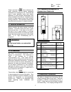
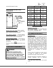
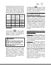
1.2.1 MINIMUM CLEARANCES TO
COMBUSTIBLE SURFACES
Figure 1 Minimum Clearances
DIM. Description
Triple-Flex
150 - 300
A
Clearance Above Top of
Boiler
18”
B Right Side 18”
C
From Chimney or Vent
Collector Measured
Horizontally
18”
D
Left Side – Tube Access
Side On Standard
Construction
27”
E
From Chimney or Vent
Collector Measured
Vertically
18”
F
Front of Boiler – Gas Train
& Control Panel End
48”
G
Rear of Boiler Opposite
Gas Train & Control Panel
End
18”
Table 1 Minimum Clearance
1.3 RECEIVING THE BOILER
2
The boiler is shipped from the factory with (4)
shipping feet/legs bolted to the skids. These are
provided to facilitate unloading/moving with a
forklift. Lifting lugs are also provided to enable
over-head lifting. The shipping feet/legs MUST