


Date: 8-4-2010
Revision: 0
Form: 2396
WARNING:
Do not open the manual main gas cock
(Figure 7 item 4) before all pre checks,
setups, and dry runs have been
successfully completed.
With a voltmeter check for the proper incoming
main voltage and the proper control voltage from
the control circuit transformer. Refer to the
electrical wiring diagram and boiler-rating label
for proper voltages.
Make sure the boiler is full of water and proper
flow has been established.
Power up the boiler see (paragraph 2.2.1).
Navigate to the ‘Operation Screen’ (paragraph
2.2.11). Select the burner switch to toggle the
burner to the off state.
Navigate to the ‘Firing Rate Control Page’
(paragraph 2.2.14). Select the ‘Manual in Run”
option and enter the light off RPM from (Table 9
Approximate Boiler Settings) in the Manual
Firing Rate box. This will prevent the burner
from ramping up to high fire after the flame
stabilization period.
Navigate to the ‘Annunciation Page” (paragraph
2.2.12). All load control inputs and interlocks
should be in the on state with the exception of
the air flow switch. The air flow switch will close
when the burner is commanded to start. Correct
any problem indicated. Refer to trouble shooting
(paragraph 0) for further help.
Navigate to the ‘Operation Screen’ (paragraph
2.2.11). The boiler is now prepared to be placed
in the on state by toggling the burner switch to
on.
2.3.4 DRY RUN
Navigate to the ‘Operation Screen’ (paragraph
2.2.11). Toggle the burner switch to on.
Navigate to the ‘Status Page’ (paragraph 2.2.5).
If there is demand for hot water the burner state
will display driving to purge. When the fan
speed is within +/- 3% of the firing rate for 3
seconds the purge timer will start and count to
30. After 30 seconds the fan speed is reduced
to the light off rate. When the fan speed is with
in +/- 3% of the firing rate for 3 seconds the
ignition transformer and the pilot valve are
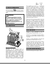
energized. The pilot will light and can be
observed from the observation port (Figure 5
item 4). After a duration of 5 seconds the
ignition transformer will de-energize. The pilot
valve will stay energized for another 5 seconds
before the main gas valves are energized.
During this 10 second period the pilot should be
djusted according to paragraph 2.3.5.
Flame lost in Main Flame
stablishing Period.
a
The main gas valves will energize for 10
seconds. After this 10 second duration the pilot
valve is de-energized. The control will lockout
with a code of 106,
E
WARNING:
During the first 10 seconds of this
process the automatic gas valves
should not have opened or been
energized. If any of the automatic gas
valves are energized or open at this
point correct the problem immediately.
2.3.5 PILOT ADJUSTMENT
Adjust the pilot gas pressure between 3.5 iwc
and 4 iwc. The pilot flame signal can be
observed from the status page (paragraph
2.2.5). The minimum flame signal is .8 volts.
The flame signal can vary between 4 volts and
15 volts. A flame signal closer to 15 volts is
preferred. Observe the pilot flame through the
flame observation port (Figure 5 item 4). The
pilot should appear stable. A stable pilot will not
flicker on and off. Recycle the boiler as many
times as needed to establish a good pilot. If the
pilot fails to light refer to trouble shooting
aragraph 1.1.1) for further help.
36
(p