


Manual 2100-549G
Page 9 of 59
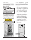
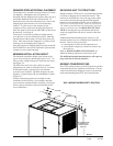
REQUIRED STEPS AFTER FINAL PLACEMENT
The compressor is secured to the base with two (2) bolts
for shipping. Although the unit will perform as
designed with the shipping bolts in place, there may be a
noticeable additional noise and vibration noted. To
obtain the lowest noise and vibration levels, remove the
shipping bolts after the unit is in its final operating
location. To gain access to the compressor, the
compressor access panel must be removed (Figure 9).
Once this panel is removed, the CRV/ERV air duct must
be removed. See Figure 6.
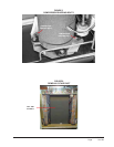
The air duct is removed by pulling it straight toward
you; there are no screws securing it in place. Both the
top and bottom slide toward you at the same time (pull
hard). Once removed, the compressor is visible as well
as the tags on the shipping bolts (Figure 5).
After the compressor shipping bolts have been removed,
the CRV/ERV air duct can be slid back in place and the
compressor access panel attached.
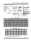
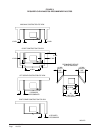
MINIMUM INSTALLATION HEIGHT
The minimum installation height to the bottom of the
roof or fixed ceiling for ducted applications is 9 ft. 7 in.
This provides enough clearance to install the duct work.
See Figure 7A.
The IWS Series wall sleeve has a built-in vertical
adjustment to fit window sill heights from 31-34 inches.
If additional height is required, two riser platform
accessories are available. The IRP3 increases the unit
height by 3 inches (Figure 7B) and the IRP6 by 6 inches
(Figure 7C).
Several construction options are available for unit
installation of the IZ Series. Serviceability and filter
access must be considered before installing. See Figure
5D for required clearances and recommended service
access dimensions.
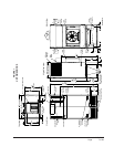
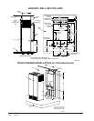
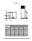
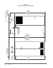
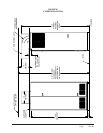
SECURING UNIT TO STRUCTURE
Shipped with the I-TEC unit is a wall mounting bracket
(screwed to shipping skid on backside of unit). This
bracket can be utilized to secure the top portion of the
unit to the wall using the appropriate field supplied
hardware based upon the material you are fastening to.
(There are several offset holes, sized to accept up to a
1/4" diameter fastener that will easily allow you to hit
studs on a framed wall.) See BRACKET SECTION
VIEW for locating this top wall bracket which will
need to be applied after the unit is located in the final
position.
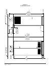
Additional/optional mounting holes for up to a 3/8"
diameter fastener are also available in the backside of
the unit. These can be accessed by:
• removing the air filters for the uppermost set
• removing the compressor section service door for
the lower set
Refer to WOOD FRAMED INSTALLATION for
additional framing required to secure unit to wall.
The additional/optional mounting holes will require a
long extension to drive the fasteners.
SEISMIC CONSIDERATIONS
The I-TEC product features several locations for product
securement but all site conditions are different. Consult
with a licensed Seismic Engineer to advise of particular
needs when attaching the I-TEC unit to the structure.
MIS-3029
2"
1 11/16"
43 3/8"
Ø1/4"
94" FROM BOTTOM
OF BRACKET TO
FLOOR WITHOUT
RISER KIT
7/8"
3/4"
1 1/2"
BRACKET
WALL MOUNTING BRACKET LOCATION