


Manual 2100-549G
Page 37 of 59
I-TEC
COMBINATION CRV &
ECONOMIZER VENTILATION SYSTEM
DESCRIPTION
The I-TEC combination Commercial Room Ventilator
(CRV) and Dry Bulb Economizer is designed to be used
with all Bard I-TEC models. This ventilation package
and its control provides two (2) roles:
•
It will provide the required ventilation by delivering
fresh air to meet I.A.Q. (Indoor Air Quality)
requirements through CRV portion of the device.
•
It will provide up to 525 CFM of free outdoor
cooling CFM when the outdoor ambient temperature
is below the outdoor thermostat setpoint.
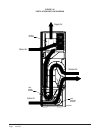
Ventilation is accomplished with (2) blower/motor
assemblies for maximum ventilation at low sound
levels. The intake and exhaust blowers are
programmed independently and are balanced to
maintain a slight positive pressurization in accordance
to ASHRAE 62.1 Standard.
The Ventilation Package is also provided with filters to
reduce the required service needed and to further
improve the I.A.Q. The exhaust air blowers are
protected by disposable filters, and the intake air
blowers are protected by washable filters. Both are
accessible without the need for tools.
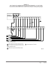
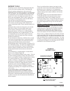
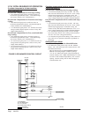
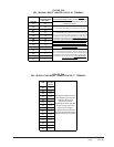
CONTROL WIRING
Refer to Low Voltage Connection (Figure 19).
Reference Figure 23 for Control Sequence of
Operation.
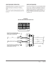
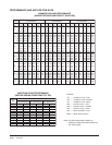
SETTING THE VENTILATION CFM
LEVELS
The I-TEC CRV has four (4) pre-set levels of
ventilation CFM available. These are 300, 375, 450
and 525 CFM of ventilation air. This ventilation
package is shipped from the factory set on the 375 CFM
ventilation level while the Economizer portion is set on
the 525 CFM ventilation level. To change between
these four different levels of provided ventilation CFM,
refer to Figure 24 to look up the corresponding CFM
needed for the intake and exhaust blowers to meet the
design criteria and determine which “speed/wire color”
is needed.
Perform the following steps:
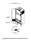
1. Open front swinging doors of main unit (by
popping front door latches).
2. Throw main power disconnect to the “OFF”
position to eliminate risk of injury or death due to
electrical shock.
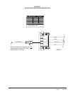
3. Remove six (6) screws holding front CRV door in
place (see Figure 22).
4. For CRV blower speed, locate “Brown Wire with
White Trace” that has as black terminal on the end
where it connects to the terminal strip (see Figure
24).
5. Move the “Brown Wire with White Trace” to the
corresponding CFM level needed in accordance
with Figure 24.
6. For Economizer Blower Speed, locate “Pink
Wire” that has a black terminal on the end where
it connects to the terminal strip (see Figure 24).
7. Move the “Pink” to the corresponding CFM level
needed in accordance with Figure 24.
Operating the
I-TEC
CRV during unoccupied
periods can result in a build up of excess
moisture in the structure.
Open disconnect to shut all power OFF before
doing this! Failure to do so could result in injury
or death due to electrical shock.