


Manual 2100-549G
Page 46 of 59
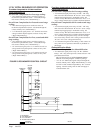
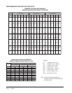
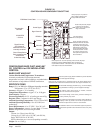
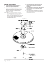
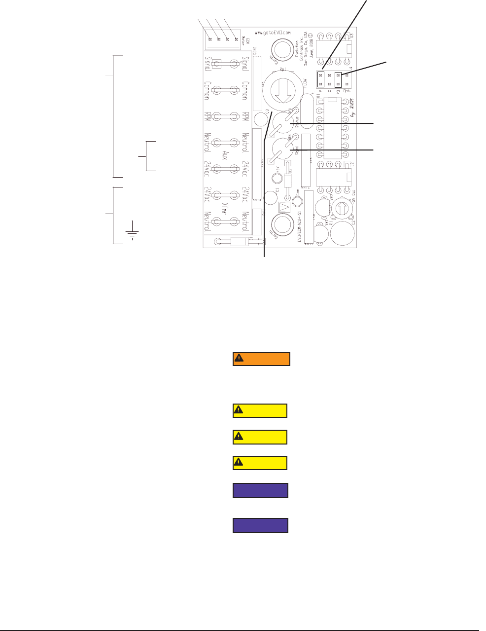
FIGURE 28
CONTROL BOARD CONFIGURATION/SETTING
CONFIGURING BARD PART #8403-067
CO
2
CONTROL for ERV MODULATING
CONTROL
BARD PART #8403-067
Carbon Dioxide and Temperature Transmitters
accurately monitorthe CO2concentration and
temperature in schools, office buildings, and otherindoor
environments to help achieve LEED® certification.
SPECIFICATIONS
Range: CO
2
: 0 to 2000 or 0 to 5000 ppm (depending on model)
Temperature: 32 to 122°F (0 to 50°C).
Accuracy: ±40 ppm + 3% of reading.
Temperature Dependence: ±8 ppm / °C at 1100 ppm.
Non-Linearity: 16 ppm.
Pressure Dependence: 0.13% of reading per mm of Hg.
Response Time: 2 minutes for 99% step change.
Ambient Operating Temperature: 32 to 122°F (0 to 50°C).
Ambient Operating Humidity: 10 to 95% RH (non-
condensing).
Power Requirements: 16 to 35 VDC / 19 to 28 VAC.
Power Consumption: Average: 2 watts; Peak: 3.75 watts.
Sensor: Single beam, dual-wave length NDIR.
Output:
Current: 4 to 20 mA (max 500
Ω
);
Voltage: 0 to 5 VDC or 0 to 10 VDC (min 500
Ω
);
Relay: SPST NO 2A @ 30 VDC;
RTD or thermistor per r-t curves (depending on model)
Weight: 5.6 oz (158.8 g)
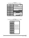
RPM Out
Neutral/Common
24Vac/dc
24Vac/dc
Common
Signal Common
Control Signal
Class II Power Source
Earth neutral/Common
at transformer
for electrical safety.
Signal Common,
Aux Common &
Neutral/Common are
internally connected
Aux
Power
ECM Motor Control Cable
To Automation
Controller
0-2,000 RPM
= 0-10Vdc
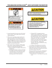
Disconnect power supply before installation to prevent electrical
shock and equipment damage.
Make sure all connections are in accordance with the job wiring diagram and in
accordance with national and local electrical codes. Use copper conductors only.
Use electrostatic discharge precautions (e.g., use of wrist straps)
during installation and wiring to prevent equipment damage.
Avoid locations where severe shock or vibration, excessive
moisture or corrosive fumes are present.
Do not exceed ratings of this device, permanent damage not
covered by warranty may result.
Upon powering the transmitter, the firmware version will flash on
the display. A warm up period of 30 minutes is required for the
transmitter to adjust to the current CO
2 concentration.
Self calibration feature of the transmitter requires exposure to
normal outdoor equivalent carbon dioxide level once every thirty
days.
WARNING
CAUTION
CAUTION
CAUTION
NOTICE
NOTICE
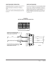
Move jumper pin to “P” position to
allow variable ventilation control
using 4-20MA CO2 controller
Board mode pins factory shipped
on “M” pin for On/Off control
scheme using “A” signal on low
voltage control board.
“Red” status light (on
when unit has power)
“Green” signal light continuously
indicates the flow index the blower
is producing. After a pause, the
lamp will flash out long digits which
will indicate the “TENS” count,
which is immediately followed by
short flashes between 1 and 99.
For example, a flow index of 23
would yield two long flashes and
three short flashes.
Manual adjust screw. Use when operating in manual mode (“M” jumper
installed) along with the “GREEN SIGNAL LIGHT” to adjust to the
required CFM of ventilation. CW rotation reduces the “FLOW INDEX”,
CCW rotation increases the “FLOW INDEX”.