


Manual 2100-549G
Page 22 of 59
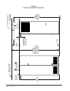
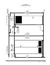
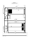
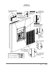
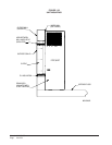
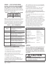
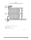
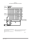
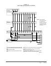
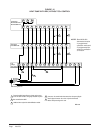
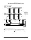
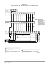
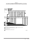
The standard unit includes a remote thermostat connection
terminal strip. See Figures 13 through 19 for connection
diagrams. Compatible thermostats are listed in Table 4.
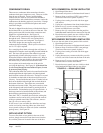
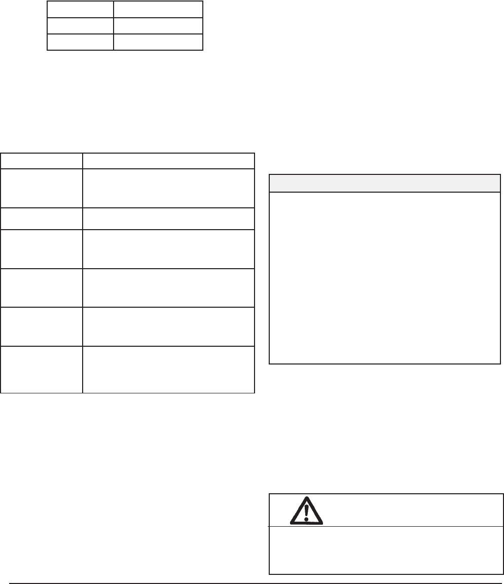
TABLE 3 — OPERATING VOLTAGE RANGE
NOTE: The voltage should be measured at the field power
connection point in the unit and while the unit is operating
at full load (maximum amperage operating condition).
PATEGNAR
V042612–352
V802781–022
WIRING – LOW VOLTAGE WIRING
230/208V, 1 PHASE AND 3 PHASE EQUIPMENT
DUAL PRIMARY VOLTAGE TRANSFORMERS.
All Equipment leaves the factory wired on 240V tap.
For 208V operation, reconnect from 240V to 208V tap.
The acceptable operating voltage range for the 240 and
208V taps are as noted in Table 3.
LORTNOCCDDROFSNOITCENNOCEGATLOVWOL
ylnOnaFGezigrenE
daoLtraPgnilooC1Y,GezigrenE
daoLlluFgnilooC2Y,1Y,GezigrenE
daoLtraPgnitaeHPH1W/B,1Y,GezigrenE
daoLlluFgnitaeHPH1W/B,2Y,1Y,GezigrenE
taeHcirtcelE+daoLlluFgnitaeHPH
)WK01otpu(
2W,1W/B,2Y,1Y,GezigrenE
ylnOtaeHcirtcelE1#knaBhtiwgnitaeH2W,GezigrenE
(taeHycnegremE noitarepopmuptaeH
noitidnocsihtrofdetagensi )
3W,2W,GezigrenE
noitalitneVAezigrenE
noitacifidimuheD
*
*
ylnOnoitacifidimuheDhtiwsledoM
D,GezigrenE
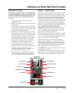
LOW VOLTAGE CONNECTIONS
These units use a grounded 24 volt AC low voltage circuit.
“G” terminal is the fan input.
“Y1” terminal is the compressor part load input.
“Y2” terminal is the compressor full load input.
“B/W1” terminal is the reversing valve input.
The reversing valve must be energized for heating mode.
“R” terminal is 24 VAC hot.
“C” terminal is 24 VAC grounded.
“L” terminal is compressor lockout output. This
terminal is activated on a high or low pressure trip and
condensate overflow trip by the electronic heat pump
control. This is a 24 VAC output.
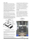
GENERAL
This unit is equipped with a variable speed ECM motor.
The motor is designed to maintain rated airflow up to
the maximum static allowed. It is important that the
blower motor plugs are not plugged in or unplugged
while the power is on. Failure to remove power prior
to unplugging or plugging in the motor could result in
motor failure.
TABLE 4 — WALL THERMOSTATS
tatsomrehTserutaeFtnanimoderP
060-3048
)544-0211(
taeHegats3;looCegats3
cinortcelEelbammargorP-noN/elbammargorP
lanoitnevnoCroPH
revoegnahclaunaMrootuA
760-3048
)YLR-DCL-04W2-TDC(
rofDCLhtiwrosneSedixoiDnobraC
sgnidaeRrosneS
OHT-B9SC
,vnoCroPH,gorPnoN/gorP,looCegatS3,taeHegatS3
/wrosneSytidimuH,revoegnahClaunaMrootuA
gninraeLtnegilletnI/wrosneSnoitoM,noitacifidimuhed
elbitapmoc-tenCAB,lortnoC
COHT-B9SC
,vnoCroPH,gorPnoN/gorP,looCegatS3,taeHegatS3
/wrosneSytidimuH,revoegnahClaunaMrootuA
/wrosneSnoitoM,rosneS2OC,noitacifidimuhed
elbitapmoc-tenCAB,lortnoCgninraeLtnegilletnI
OHT-EB9SC
,vnoCroPH,gorPnoN/gorP,looCegatS3,taeHegatS3
/wrosneSytidimuH,revoegnahClaunaMrootuA
gninraeLtnegilletnI,rosneSnoitoM,noitacifidimuhed
elbitapmoc-tenrehtE,elbitapmoc-tenCAB,lortnoC
COHT-EB9SC
,vnoCroPH,gorPnoN/gorP,looCegatS3,taeHegatS3
/wrosneSytidimuH,revoegnahClaunaMrootuA
/wrosneSnoitoM,rosneS2OC,noitacifidimuhed
,elbitapmoc-tenCAB,lortnoCgninraeLtnegilletnI
elbitapmoc-tenrehtE
“W2” terminal is first stage electric heat (if equipped).
First stage electric heat can be operated simultaneously
with the heat pump operating.
“A” terminal is the ventilation input. This terminal
energizes any factory installed ventilation option.
“W3” terminal is second stage electric heat. When
“W3” terminal is energized, it locks out compressor
operation to limit discharge air temperature and required
branch circuit ampacity.
“D” terminal is the dehumidification mode (on models
so equipped).
NOTE: For total and proper control using DDC, a
minimum of 9 controlled outputs are needed when above
10KW Electric Heat is employed with ventilation, a
total of 8 controlled outputs with below 10KW Electric
Heat with Ventilation, 7 controlled outputs below 10KW
Electric Heat with no ventilation, 7 controlled outputs
with no Electric Heat, but with ventilation, and 6
controlled outputs with no electric heat and no
ventilation. If Dehumidification Model & Vent, 10
controlled outputs are needed when above 10KW
Electric Heat is employed with ventilation.
CAUTION
Do not plug in or unplug blower motor
connectors while the power is on. Failure to do
so may result in motor failure.