


Manual 2100-549G
Page 41 of 59
RECOMMENDED CONTROL SEQUENCES
Several possible scenarios are listed below:
1. Use a programmable electronic thermostat with
auxiliary terminal to control the ERV based on
daily programmed occupance periods. Bard
markets and recommends Bard Part #8403-060
programmable electronic thermostat.
2.
Use a motion sensor in conjuntion with a mechanical
thermostat to determine occupancy in the structure.
Bard markets the CS2000A for this use.
3.
Use a DDC control system to control the ERV based
upon a room occupancy schedule to control the ERV.
4.
Tie the operation of the ERV into the light switch. The
lights in a room are usually on only when occupied.
5. Use a manual timer that the occupants turn to
energize the ERV for a specific number of hours.
6. Use a programmable mechanical timer to energize
the ERV and indoor blower during occupied
periods of the day.
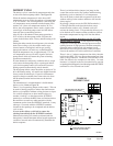
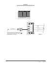
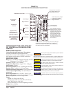
NOTE: The ventilation package comes with a blower
interlock function, but is disabled when it is shipped from the
factory in case you do not utilize a thermostat with an
occupancy output, or a occupancy sensor and must tie "A"
terminal to "G" terminal to drive the ventilation package. If
you
do have a thermostat or control that does drive occupancy
output, you will need to remove the tape from the orange wire
located in the low voltage terminal box, and connect it to the
"G" terminal to activate this function. (See Figures 13-19.)
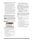
SUPPLIES BEFORE SERVICING.
!
HAZARD OF ELECTRICAL SHOCK.
ELECTRICAL SHOCK CAN RESULT
7961-754-2
WARNING
IN SERIOUS INJURY OR DEATH.
DISCONNECT THE REMOTE
ELECTRIC POWER SUPPLY OR
CHANGING VENTILATION CFM RATES IN
MANUAL MODE
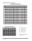
To adjust the airflow ventilation rate, first refer to
Figure 25A to look up the “FLOW INDEX” needed for
the intake and exhaust blowers for the CFM you
require. Then, perform the following steps:
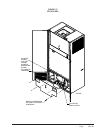
1.
Open front swinging doors of main unit (by popping
front door latches).
2. Throw main power disconnect to the
“
OFF
”
position to eliminate risk of injury or death due to
electrical shock.
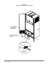
3. Remove five (5) screws holding front ERV door
in place (See Figure 27).
4. Remove ERV Control Panel Cover by removing
four (4) screws (See Figure 27).
5. Locate two 0-10Vdc Motor Control Boards in
control panel (See Figure 28).
6. On intake Motor Control Board, observing
“GREEN STATUS LIGHT”, turn manual adjust
potentiometer “CCW” to increase “FLOW
INDEX” or CW to reduce “FLOW INDEX” to
match desired setting.
NOTE: After long pause, the green status light will blink
long-blinks for the “TEN COUNT” of the “FLOW RATE
INDEX”, then immediately followed by fast blinks which
indicate the second digit. For example, a Flow Index of
23 would be two long blinks, followed by 3 fast blinks of
the “GREEN STATUS LIGHT”.
7. On exhaust Motor Control Board, observing
“GREEN STATUS LIGHT”, turn manual adjust
potentiometer “CCW” to increase “FLOW
INDEX” or CW to reduce “FLOW INDEX” to
match desired setting.
NOTE: Same “GREEN STATUS LIGHT” blink as Step #6.
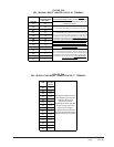
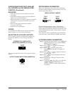
CHANGING TO FULLY MODULATING MODE
If you want to operate the ERV in fully variable mode (Fig.
25B) (only run at required speed to maintain set-point CO2
levels), you will need to configure the ERV to the
following:
1.
Open front swinging doors of main unit (by popping
front door latches).
2. Throw main power disconnect to the
“
OFF
”
position to eliminate risk of injury or death due to
electrical shock.
3. Remove ERV Control Panel Cover by removing
four (4) screws (See Figure 27).
4. Locate two 0-10Vdc Motor Control Boards in
control panel (See Figure 28).
5. Pull jumper pins from “M” terminals, and move to
“P” terminals (See Figure 28).
6. Connect “+” 0-10Vdc output from CO2 control to
Terminal #3 (along with pink wire), and connect
“-” to Terminal #4 (along with purple wire) of unit
low voltage terminal strip.
7. Follow the directions supplied with the CO2
control to configure the control appropriately.