


Manual 2100-549G
Page 6 of 59
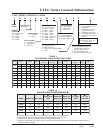
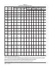
TABLE 2
ELECTRICAL SPECIFICATIONS
detaR
ztreH,stloV
esahPdna
dleiF.oN
rewoP
stiucriC
tiucriCelgniS tiucriClauD
ledoM
muminiM
tiucriC
yticapmA
mumixaM
esuFlanretxE
.rkrB.tkCro
dleiF
rewoP
eziSeriW
dnuorG
eriW
muminiM
tiucriC
yticapmA
mumixaM
esuFlanretxE
rekaerB.tkCro
dleiF
rewoP
eziSeriW
dnuorG
eriW
A.tkC B.tkC A.tkC B.tkC A.tkC B.tkC A.tkC B.tkC
Z0A-1H03I
50A
01A
1-802/032
1
1
2ro1
22
84
47
53
05
08
8
8
4
01
01
8
84 03 05 03 8 01 01 01
Z0B-1H03I
60B
90B
3-802/032
1
1
1
71
53
44
52
53
54
01
8
8
01
01
01
Z0C-1H03I
60C
90C
3-064
1
1
1
9
81
22
01
02
52
41
21
01
41
21
01
Z0A-1H63I
50A
01A
1 51A
1-802/032
1
1
2ro1
2ro1
62
25
87
48
04
06
08
09
8
6
4
4
01
01
8
8
62
62
25
25
04
04
06
06
8
8
6
6
01
01
01
01
Z0B-1H63I
60B
90B
1 51B
3-802/032
1
1
1
1
22
04
94
15
03
54
05
06
01
8
8
6
01
01
01
01
Z0C-1H63I
60C
90C
1 51C
3-064
1
1
1
1
11
02
42
82
51
02
52
03
41
21
01
01
41
21
01
01
Z0A-1H24I
50A
01A
1 51A
1-802/032
1
1
2ro1
2ro1
03
65
28
28
54
06
09
09
8
6
4
4
01
01
8
8
65
65
62
25
06
06
03
06
6
6
01
6
01
01
01
01
Z0B-1H24I
60B
90B
1 51B
3-802/032
1
1
1
1
52
34
25
25
53
05
06
06
8
8
6
6
01
01
01
01
Z0C-1H24I
60C
90C
1 51C
3-064
1
1
1
1
21
12
62
82
51
52
03
03
41
01
01
01
41
01
01
01
Z0A-1H84I
40A
50A
01A
1 51A
1 02A
1-802/032
1
1
2ro1
2ro1
2ro1
2ro1
43
45
95
58
58
011
05
06
07
09
09
011
8
6
6
3
3
2
01
01
8
8
8
6
53
53
53
95
62
25
25
25
54
54
54
06
03
06
06
06
8
8
8
6
01
6
6
6
01
01
01
01
01
01
01
01
Z0B-1H84I
60B
90B
1 51B
1 81B
3-802/032
1
1
1
1
1
62
44
35
35
35
53
05
06
06
06
8
8
6
6
6
01
01
01
01
01
Z0C-1H84I
60C
90C
1 51C
1 81C
3-064
1
1
1
1
1
51
52
92
92
92
02
03
03
03
03
21
01
01
01
01
21
01
01
01
01
Z0A-1H06I
1 44 06 8 01
50A
01A
1 51A
1 02A
1-802/032
2ro1
2ro1
2ro1
2ro1
07
69
69
211
08
001
001
021
4
3
3
2
8
8
8
6
44
44
44
06
62
25
25
25
06
06
06
06
03
06
06
06
8
8
8
6
01
6
6
6
01
01
01
01
01
01
01
01
Z0B-1H06I
1 13 54 8 01
60B
90B
1 51B
1 81B
3-802/032
1
1
1
2ro1
94
85
85
36
06
06
06
07
8
6
6
6
01
01
01
8
13 45 54 06 8 6 01 01
Z0C-1H06I
1 51 02 21 21
60C
90C
1 51C
1 81C
3-064
1
1
1
1
52
92
92
92
03
03
03
03
01
01
01
01
01
01
01
01
These “Minimum Circuit Ampacity” values are to be used for sizing the field power conductors. Refer to the National Electric Code (latest
revision), article 310 for power conductor sizing.
Caution: When more than one field power conductor circuit is run through one conduit, the conductors must be derated. Pay special
attention to note 8 of table 310 regarding Ampacity Adjustment Factors when more than three conductors are in a raceway.
Maximum size of the time delay fuse or HACR type circuit breaker for protection of field wiring conductors.
Based on 75°C copper wire. All wiring must conform to the National Electrical Code and all local codes.
Maximum KW that can operate with heat pump on is 10KW for 1-Phase and 9KW for 3-Phase.
1 Represents Electric Heat Only. Electrical Control Circuit will lockout Heat Pump Operation.