


Manual 2100-549G
Page 17 of 59
DUCT WORK
Any heat pump is more critical of proper operating
charge and an adequate duct system than a straight air
conditioning unit. All duct work must be properly sized
for the design airflow requirement of the equipment.
Air Conditioning Contractors of America (ACCA) is an
excellent guide to proper sizing. All duct work or
portions thereof not in the conditioned space should be
properly insulated in order to both conserve energy and
prevent condensation or moisture damage. When duct
runs through unheated spaces, it should be insulated
with a minimum of one inch of insulation. Use
insulation with a vapor barrier on the outside of the
insulation. Flexible joints should be used to connect the
duct work to the equipment in order to keep the noise
transmission to a minimum.
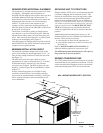
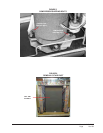
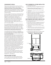
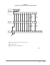
The I-TEC series heat pump has provision to attach a
supply air duct to the top of the unit. Duct connection
size is 20 inches x 24 inches. The flanges are shipped
flat and must be bent upward using sheet metal flanging
pliers. The duct work is field supplied. See Figure 8 for
suggested attachment method.
Make sure to seal the slots in the bend-up flange at the
time of securing your ductwork to the flange. This can
be accomplished with either foil tape or caulk. Failing
to do so may cause air leakage/whistling of air.
NOTE: Unit cabinet, supply air duct and duct free
plenum are approved for “0” clearance to
combustible material.
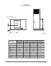
The I-TEC series heat pumps are designed for use with
free return (non-ducted) and either duct free with the use
of IPBDF Series Plenum Box (8" or 12") or a duct
supply air system.
The IPBDF Plenum Box mounts on top of the unit and
has both vertically and horizontally adjustable louvers on
the front discharge grille.
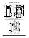
When used with a ducted supply, an ICX9 or ICX10
Cabinet Extension may be used to conceal the
ductwork above the unit to the ceiling. The ICX9
extends 20" above the unit for a total height of 9'-6" for
a floor mounted install (9'-9" with IRP3 riser & 10'-0"
with IRP6 riser). The ICX10 extends 28" above the unit
for a total height of 10'-2" for a floor mounted install
(10'-5" with IRP3 riser & 10'-8" with IRP6 riser).
The unit is equipped with a variable speed indoor
blower motor which increases in speed with an increase
in duct static pressure. The unit will therefore deliver
proper rated airflow up to the maximum ESP shown in
Table 1A. However, for quiet operation of the air
system, the duct static should be kept as low as
practical, within the guidelines of good duct design.
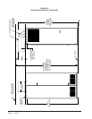
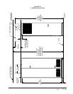
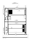
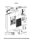
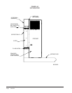
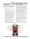
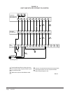
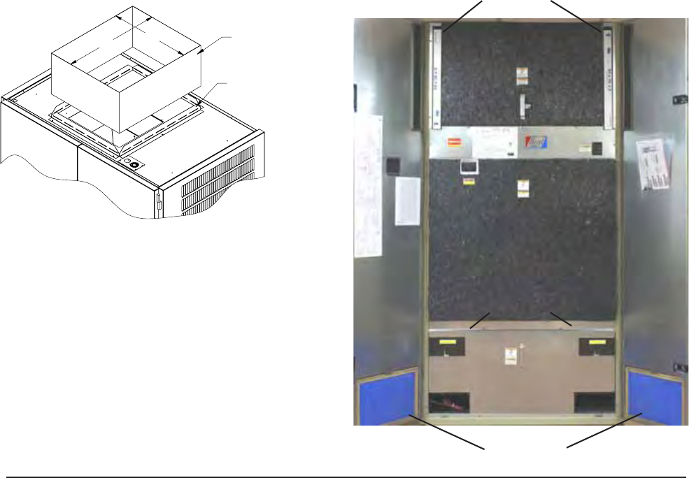
FILTERS
Two 2-inch throw away filters (24 x 30) and two 1-
inch throw away filters (12 x 20) are supplied with
each unit. The 2-inch filters slide into brackets on
both sides for the return air openings. The 1-inch
filters are in the cabinet doors for the vent (room air)
exhaust. If a CRV or ERV vent option is used, there
are two (2) additional ½" (8 x 17) washable filters
included with that option. See Figure 9 for specific
locations. The filters are serviced from the inside of
the building by opening the cabinet doors, and do not
require any tools to access.
MIS-2959
SUPPLY DUCT AND
FASTENERS TO BE
FIELD SUPPLIED
24"
20"
BEND THE PROVIDED
SUPPLY FRAME FLANGES
UP FOR DUCT INSTALLATION
FIGURE 8
SUPPLY DUCT CONNECTIONS
FIGURE 9
FILTER LOCATION
É
É
É
É
É
É
12" X 20" X 1"
FILTERS
24" X 30" X 2"
FILTERS
ACCESS TO
WASHABLE
FILTERS
COMPRESSOR
ACCESS
INDOOR
BLOWER
ACCESS
VENT
OPTION
ACCESS