


Manual 2100-549G
Page 56 of 59
TROUBLESHOOTING INDOOR ECM
™
BLOWER MOTORS
(Cont’d.)
Replacing ECM Control Module
To replace the control module for the GE variable-speed indoor blower
motor you need to take the following steps:
1. You MUST have the correct replacement module. The controls are
factory programmed for specific operating modes. Even though they look
alike, different modules may have completely different functionality.
USING THE WRONG CONTROL MODULE VOIDS ALL PRODUCT
WARRANTIES AND MAY PRODUCE UNEXPECTED RESULTS.
2. Begin by removing AC power from the unit being serviced. DO NOT
WORK ON THE MOTOR WITH AC POWER APPLIED. To avoid
electric shock from the motor’s capacitors, disconnect power and wait at
least 5 minutes before opening motor.
3. It is not necessary to remove the motor from the blower assembly, nor
the blower assembly from the unit. Unplug the two cable connectors to the
motor control assembly. There are latches on each connector. DO NOT
PULL ON THE WIRES. The plugs remove easily when properly
released.
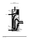
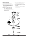
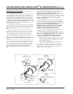
4. Locate the screws that retain to t
he motor control bracket to the
sheet metal of the unit and remove them. Remove two (2) nuts that
retain the control to the bracket and then remove two (2) nuts that
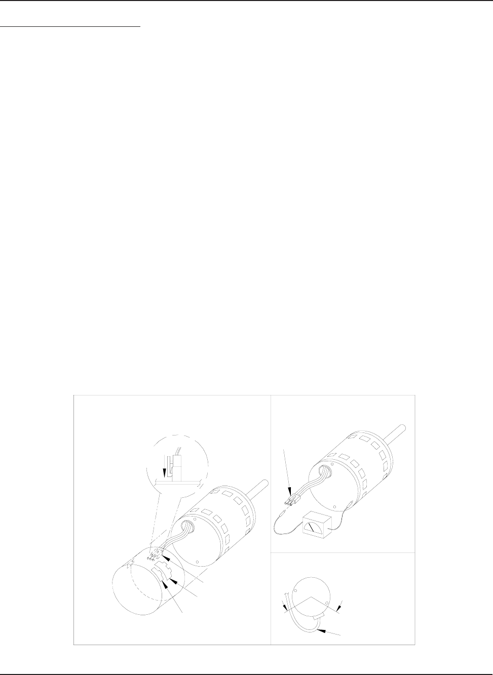
retain sheet metal motor control end plate. Refer to Figure 30.
5. Disconnect the three (3) wires interior of the motor control by
using your thumb and forefinger squeezing the latch tab and the
opposite side of the connector plug, gently pulling the connector. DO
NOT PULL ON THE WIRES, GRIP THE PLUG ONLY. Refer to
Figure 30.
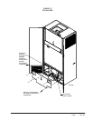
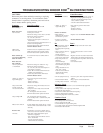
6. The control module is now completely detached from the motor.
Verify with a standard ohmmeter that the resistance from each motor
lead (in the motor plug just removed) to the motor shell is >100K
ohms. Refer to Figure 31. (Measure to unpainted motor end plate.) If
any motor lead fails this test, do not proceed to install the control
module. THE MOTOR IS DEFECTIVE AND MUST BE
REPLACED. Installing the new control module will cause it to fail
also.
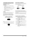
7. Verify that the replacement control is correct for your
application. Refer to the manufacturer's authorized replacement list.
USING THE WRONG CONTROL WILL RESULT IN
IMPROPER OR NO BLOWER OPERATION. Orient the control
module so that the 3-wire motor plug can be inserted into the socket in
the control. Carefully insert the plug and press it into the socket until
it latches. A SLIGHT CLICK WILL BE HEARD WHEN
PROPERLY INSERTED.
8. Reverse the steps #5, 4, 3 to reconnect the motor control to the
motor wires, securing the motor control cover plate, mounting the
control to the bracket, and mounting the motor control bracket back
into the unit. MAKE SURE THE ORIENTATION YOU SELECT
FOR REPLACING THE CONTROL ASSURES THE
CONTROL'S CABLE CONNECTORS WILL BE LOCATED
DOWNWARD IN THE APPLICATION SO THAT WATER
CANNOT RUN DOWN THE CABLES AND INTO THE
CONTROL. DO NOT OVERTIGHTEN THE BOLTS.
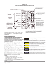
9. Plug the 16-pin control plug into the motor. The plug is keyed.
Make sure the connector is properly seated and latched.
10. Plug the 5-pin power connector into the motor. Even though
the plug is keyed, OBSERVE THE PROPER ORIENTATION. DO
NOT FORCE THE CONNECTOR. It plugs in very easily when
properly oriented. REVERSING THIS PLUG WILL CAUSE
IMMEDIATE FAILURE OF THE CONTROL MODULE.
11.
Final installation check. Make sure the motor is installed as follows:
a. Motor connectors should be oriented between the 4 o’clock
and 8 o’clock positions when the control is positioned in its
final location and orientation.
b.Add a drip loop to the cables so that water cannot enter the
motor by draining down the cables. Refer to Figure 32.
The installation is now complete. Reapply the AC power to the
HVAC equipment and verify that the new motor control module is
working properly. Follow the manufacturer's procedures for
disposition of the old control module.
Motor
Motor OK when
R > 100k ohm
ECM 2.0
Only remove
Hex Head Bolts
Connector Orientation
Between 4 and 8 o'clock
Drip Loop
Back of
Control
Figure 5
Winding Test
Figure 4
Note:
Use the shorter
bolts and
alignment pin
supplied when
replacing an
ECM 2.0
control.
Figure 3
ECM
2.3/2.5
Power Connector
(5-pin)
Control Connector
(16-pin)
Hex-head Screws
Motor Connector
(3-pin)
Motor Connector
(3-pin)
Control Disassembly
Drip Loop
Push until
Latch Seats
Over Ramp
From Motor
Circuit
Board
Figure 31
Figure 30
Figure 32
EON
5.0