


Manual 2100-549G
Page 18 of 59
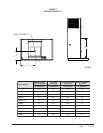
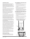
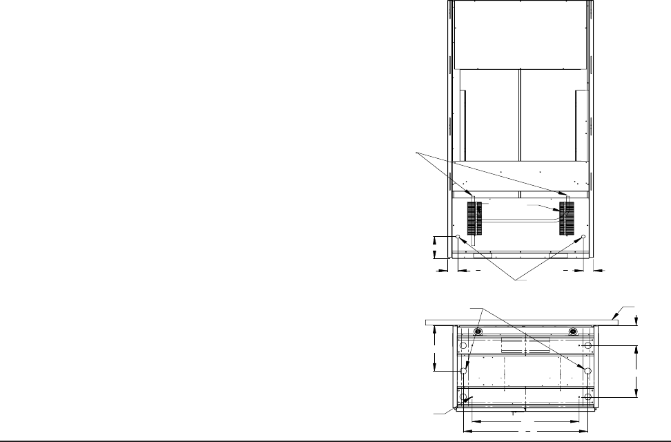
(2)OPTIONAL
DRAIN HOLES
OPTIONAL FLOOR
MOUNTING HOLES
18 3/4"
WALL
35"
"
4
3
40
7 3/16"
16 1/2"
Entrances
Unit Drain
(2) Unit Drains
(2) Optional
Drain Access
Locations
3
"
8
3
8"
3
3
8
"
MIS-2960 B
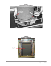
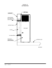
CONDENSATE DRAIN
There are two condensate drain connections from the
condenser drain pan (compressor area). These are visible
from the rear of the unit. Factory installed tubing
connects the two drains at a tee connection and then a
single drain hose with a barbed hose connector carries the
condensate to the draining option of your choice. Enough
tubing is provided to reach all drain options and can be
cut down in length.
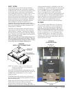
The unit is shipped from the factory with the drain line on
the left-hand side as you look at the rear of the unit. The
tubing can be removed from the drain connections and
flipped for a right-hand drain. See Figure 10.
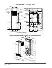
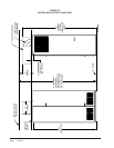
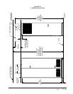
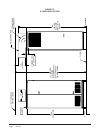
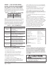
The drain can be routed directly through the floor or
through the wall. There are also two optional drain
locations in the lower rear back panel. See Figure 8.
The I-TEC design does not require a trap in the
condensate disposal tubing. Check your local codes to
see if a “P” trap is required.
For a stand pipe floor drain or through the wall, there is
adequate hose length to reach anything located behind the
unit. The lower rear portion of the cabinet is recessed
approximately 4 inches allowing room for a “P” trap to
be installed with the cabinet flush with the wall. Keep in
mind, the drain line must be able to be removed from the
unit if necessary to remove the unit from the wall.
Access plates are located on the rear of the unit for
servicing the drain trap. See Figure 10. If the drain line
is to be routed through an unconditioned space, it must
be protected from freezing.
The condensate drain line can also be routed back into the
unit through either the right-hand or left-hand optional
drain locations on the rear of the unit. The hole is covered
by insulation on the inside of the unit and will have to be
cut away. Located inside the unit, about 12 inches in from
the front on both the left and right side are drain holes in
the bottom of the base. These holes are covered with
insulation and are not visible. They are located very close
to the side panels and can be found by pressing down on
the insulation. Cut insulation away to expose the hole. A
drain trap can now be installed inside of the cabinet, and
the drain hose routed directly through the floor.
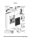
Once the I-TEC is installed, the rear drains exiting the
condenser section can be easily serviced with removal
of the pre-painted metal sides (lift-off doors, remove
four [4] screws to remove side).
If side access is not available, the drain lines and trap
can be serviced by removing either one of the drain
access panels on the rear of the unit (in the ventialtion
package area.) See Figure 10.
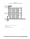
WITH NO VENT OPTION
To access the drain access panels in the rear of this
section, simply remove the front door/cover from the
box, and the plates are located in the rear of the box.
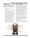
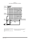
WITH COMMERCIAL ROOM VENTILATOR
1. Open hinged front doors.
2. Disconnect unit power to eliminate shock hazard.
3. Remove front cover/door of CRV vent package.
(Can leave filter access panels in place.)
4. Unplug wires coming in on left side from upper
unit section.
5.
Unplug two wire harness from front (intake) blower.
6. Remove two (2) screws securing front (intake)
blower and slide blower out of unit.
7. Remove four (4) screws that retian the partition
behind/beneath intake blower removed in Step #6.
8. Rear drain access panels are now visible on both
right-hand and left-hand sides in rear of box.
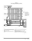
WITH ENERGY RECOVERY VENTILATOR
To access the rear drain access panels of this section:
1. Open hinged front doors.
2. Disconnect unit power to eliminate shock hazard.
3. Remove front cover/door of ERV vent package.
(Can leave filter access panels in place.)
4. Unplug wires coming in on left side from upper
unit section.
5.
Unplug heat recovery cassette on the side you wish
to access, and slide cassette out the front of the unit.
6. Remove two (2) screws securing partition on
outboard side of cassette and remove.
7. Rear drain access panels are now visible on both
right-hand and left-hand sides in rear of box.
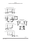
FIGURE 10 — DRAIN LOCATIONS