


Manual 2100-549G
Page 2 of 59
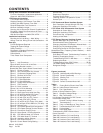
CONTENTS
Getting Other Information and Publications
For more information, contact these publishers: .......... 3
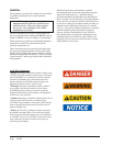
General & ANSI Z535.5 Definitions ............................. 4
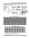
I-TEC General Information
I-TEC Model Nomenclature .......................................... 5
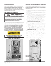
Shipping Damage, Unit Removal From Skid ............... 8
Handling Unit After Removal From Skid....................... 8
Required Steps after Final Placement.......................... 9
Minimum Installation Height ......................................... 9
Securing Unit to Structure & Seismic Considerations .. 9
Duct Work, Supply Duct Connections & Filters.......... 17
Condensate Drain ...................................................... 18
With No Vent Option and With CRV & ERV ............... 18
Installation Instructions
Mounting the Unit & Wiring — Main Wiring ................ 21
Wiring—Low Volt. Wiring & Low Volt.Connections .... 22
Start Ups
R-410A Refrigerant Required ..................................... 30
Topping Off System Charge ....................................... 30
Safety Practices ......................................................... 30
Description of Standard Equipment............................ 31
Important Installer Note .............................................. 31
Phase Monitor ............................................................ 31
Three Phase Scroll Compressor ................................ 31
Service Hints .............................................................. 31
Sequence of Operation .............................................. 32
Pressure Service Ports............................................... 32
Lowering Outdoor Fan Speed for Sound.................... 32
Defrost Cycle .............................................................. 33
I-TEC Commercial Room Ventilator System
Gen. Description, Control Wiring & Rec. Seq. ........... 34
Setting the Ventilation CFM Levels ............................ 34
I-TEC Comb. CRV & Economizer Vent System
Description & Control Wiring ...................................... 37
Setting the Ventilation CFM Levels ............................ 37
Economizer Seq. of Operation ................................... 38
Heating & Vent Mode ................................................. 39
I-TEC Energy Recovery Ventilator System
General Description & Control Wiring ........................ 40
Recommended Control Sequences ........................... 41
Changing Ventilation CFM Rates in Manual Mode .... 41
Changing to Fully Modulating Mode........................... 41
Configuring Control for ERV Mod. Control ............47-48
Maintenance (Gen., Frequency, Clean & Perform.) .....49-50
Troubleshooting
Solid State HP Control Troubleshooting Procedure ... 51
Checking Temperature Sensor ................................... 52
Troubleshooting ECM™ 142R Motor ................ 43 & 54
Replacing the Motor .................................................. 54
Troubleshooting Indoor ECM™ Motor .................. 55-56
Fan Blade Setting Dimensions ................................... 57
Refrigerant Charge ..................................................... 57
Figures
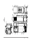
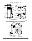
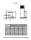
Figure 1 Unit Dimensions .......................................... 7
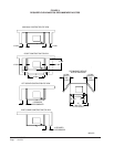
Figure 2A & 2B Unit on Lift & Unit Side ........................ 8
Wall Mounting Bracket Location .................................... 9
Bracket Wall Sect. View & Wood Framed Install ........ 10
Figure 3 Center of Gravity ....................................... 11
Figure 4 Req. Clearances & Rec. Access ............... 12
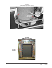
Figure 5 Compressor Shipping Bolts ....................... 13
Figure 6 Removal of Air Duct ................................... 13
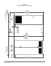
Figure 7A Ducted Application..................................... 14
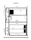
Figure 7B 3" Riser Application ................................... 15
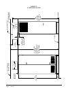
Figure 7C 6" Riser Application ................................... 16
Figure 8 Supply Duct Connections .......................... 17
Figure 9 Filter Location ............................................ 17
Figure 10 Drain Locations ......................................... 18
Figures 11A & 11B Unit Mounting ....................... 19 & 20
Figure 12 Component Location ................................. 21
Figure 13 Basic Heat Pump w/No Vent Pkg. ............. 23
Figure 14 HP w/CRV, without CO
2
Control ................. 24
Figure 15 HP with CRV & CO
2
Control ...................... 25
Figure 16 HP with ERV, w/o CO
2
Control................... 26
Figure 17 HP with ERV & CO
2
Control ...................... 27
Figure 18 HP w/ERV & CO
2
Control (Fully Mod.) ...... 28
Figure 19 HP w/Comb. CRV & DB Econ. ("N" Vent) .... 29
Figure 20 Defrost Cycle ............................................. 33
Figure 21 CRV Motor Speed/CFM Configuration ...... 35
Figure 22 CRV Speed Change Terminal Access ....... 36
Figure 23 Economizer Control Circuit ........................ 38
Figure 24 Motor Speed / CFM Configuration ............. 39
Fig. 25A ERV Manual Mode "M" Terminal ............... 43
Fig. 25B ERV Mod. Mode "P" Terminal .................... 43
Figure 26 Ventilation Airflow Diagram ........................ 44
Figure 27 ERV Control Access .................................. 45
Figure 28 Control Board Config./Setting .................... 46
Figures (continued)
Figure 29 Hub Assembly w/Ball Bearings.................. 50
Figure 30 Control Disassembly ................................. 56
Figure 31 Winding Test .............................................. 56
Figure 32 Drip Loop ................................................... 56
Figure 33 Control Connector Motor Half .................... 57
Tables
Table 1 Factory Built-In Electric Heat Table .............. 5
Table 1A Indoor Blower Performance .......................... 5
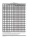
Table 2 Elec. Specifications....................................... 6
Center of Gravity Reference Table .............................. 11
Table 3 Operating Voltage Range ........................... 22
Table 4 Wall Thermostats ........................................ 22
Low Voltage Connections for DDC Control ................. 22
Performance & App. Data:
Summer Cooling & Winter Heating ............ 42
Table 5 Troubleshooting .......................................... 51
Table 6 Temp. vs Resistance of Temp. Sensor ....... 52
Table 7 Troubleshooting ECM™ 142R .................... 54
Table 8 Cooling Mode.............................................. 54
Table 9 Heat Pump Mode ........................................ 54
Troubleshooting ECM™ Blower Motors ...................... 57
Power Connector ........................................................ 57
Table 10A Pressures: Full Load Cooling ..................... 58
Table 10B Pressures: Full Load Heating ..................... 58
Table 11A Pressures: Part Load Cooling..................... 59
Table 11B Pressures: Part Load Heating .................... 59