


Manual 2100-549G
Page 43 of 59
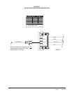
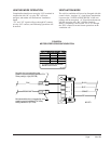
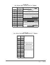
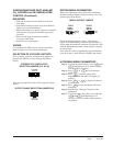
FIGURE 25A
ERV “MANUAL MODE” JUMPER PIN ON “M” TERMINAL
FIGURE 25B
ERV “MODULATING MODE” JUMPER PIN ON “P” TERMINAL
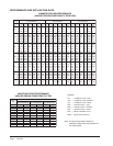
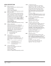
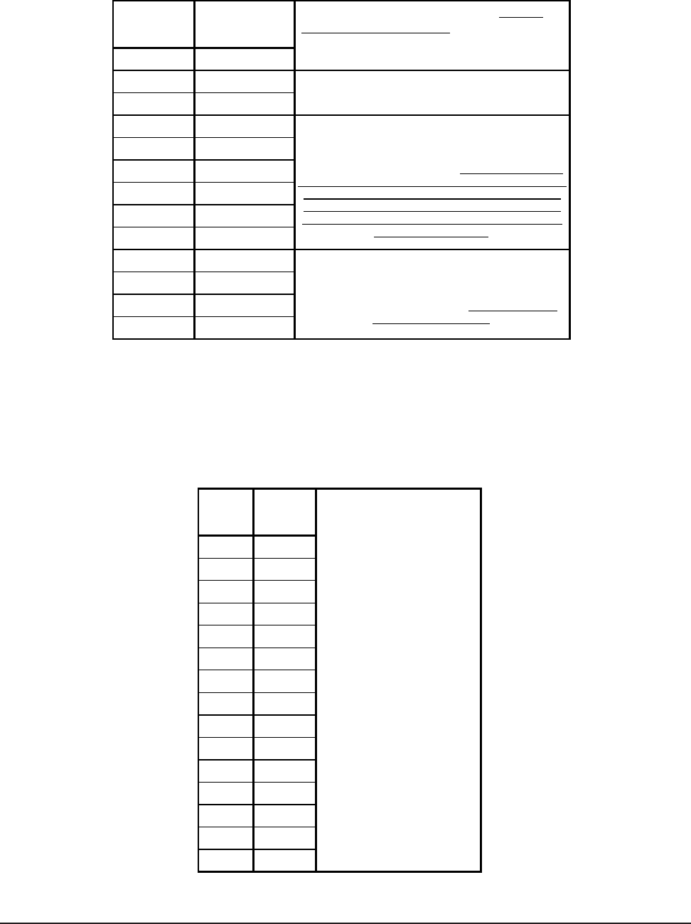
ERV CFM
FLOW INDEX (Light
Blink Code)
450 100
425 89
400 83
375 76
350 59
325 50
300 40
275 32
250 25
225 12
200 9
175 4
150 1
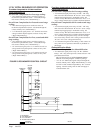
To adjust the airflow ventilation rate (NO CO2
CONTROL/NON-MODULATING) , determine the "FLOW
INDEX" needed for the intake and exhaust blowers for
the CFM you require.
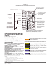
1.> Locate two 0-10Vdc Motor Control Boards in control panel
2.> On intake Motor Control Board, observing "GREEN STATUS
LIGHT", turn manual adjust potentiometer (with a small phillips-head
screwdriver) "CCW" to increase "FLOW INDEX" or CW to reduce
"FLOW INDEX" to match desired setting. (NOTE: After long pause,
the green status light will blink long-blinks for the "TEN COUNT" of
the "FLOW RATE INDEX", which then is immediately followed by
fast blinks which indicate the second digit. For example, a Flow
Index of 23 would be two long blinks, followed by 3 fast blinks of
the "GREEN STATUS LIGHT".)
3.> On exhaust Motor Control Board, observing "GREEN STATUS
LIGHT", turn manual adjust potentiometer (with a small phillips-head
screwdriver) "CCW" to increase "FLOW INDEX" or CW to reduce
"FLOW INDEX" to match desired setting. (Same GREEN STATUS
LIGHT blink (refer to Step #5))
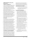
CFM
Vdc Signal
from CO2
Control
450
10
425
8.87
400
8.31
375
7.61
350
6.73
325
5.91
300
5.15
275
4.58
250
4.06
225
2.91
200
2.57
175
2.24
150
1.74
125
0.96
100
0.77
After determining the air volume
rates needed for the intended
application (Maximum &
Minimum), the table
immediately to the left will allow
for you to program your CO2
control output voltages in
correlation to the CO2 levels you
wish to control when Bard Part #
8403-067 CO2 Control is applied.