


Manual 2100-549G
Page 32 of 59
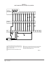
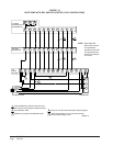
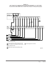
SEQUENCE OF OPERATION
COOLING PART LOAD – Circuit R-Y1 makes at
thermostat pulling in compressor contactor, starting the
compressor and outdoor motor. The G (indoor motor)
circuit is automatically completed on any call for
cooling operation or can be energized by manual fan
switch on subbase for constant air circulation.
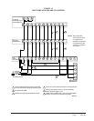
COOLING FULL LOAD – Circuit R-Y1 & Y2
makes at the thermostat energizing the 2nd stage
solenoid in the compressor. The default position of the
compressor staging solenoid is non-energized. The
compressor will run at low capacity until this solenoid is
energized.
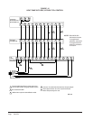
HEATING STAGE 1 – A 24V solenoid coil on
reversing valve controls heating cycle operation. Two
thermostat options, one allowing “Auto” changeover
from cycle to cycle and the other constantly energizing
solenoid coil during heating season and thus eliminating
pressure equalization noise except during defrost, are to
be used. On “Auto” option a circuit is completed from
R-B and R-Y1 on each heating “on” cycle, energizing
reversing valve solenoid and pulling in compressor
contactor starting compressor and outdoor motor. R-G
also make starting indoor blower motor. Heat pump
heating cycle now in operation. The second option has
no “Auto” changeover position, but instead energizes
the reversing valve solenoid constantly whenever the
system switch on subbase is placed in “Heat” position,
the “B” terminal being constantly energized from R. A
thermostat demand for Stage 1 heat completes R-Y1
circuit, pulling in compressor contactor starting
compressor and outdoor motor. R-G also make starting
indoor blower motor.
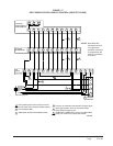
HEATING STAGE 2 – Circuit R-Y1 & Y2 makes at
the thermostat energizing the 2nd stage solenoid in the
compressor.
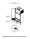
PRESSURE SERVICE PORTS
High and low pressure service ports are installed on all
units so that the system operating pressures can be
observed. Pressure tables can be found later in the
manual covering all models. It is imperative to match
the correct pressure table to the unit by model number.
Upper and lower service doors must be attached to
obtain proper reading.
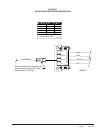
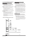
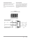
LOWERING OUTDOOR FAN SPEED for
SOUND
Supplied in the Literature Assembly is a Fan Control
Resistor Assembly that can be installed to lower the fan
speed for reduced sound performance. This Resistor
Assembly is to be installed in series with the Outdoor
Fan Control Thermistor to change the temperature curve
that the fan logic control sees.
It is anticipated that you will see a 2-3% drop in system
capacity and efficiency when this resistor is installed.
To install the Resistor Assembly:
1. Locate Fan Control Resistor Assembly in
Literature Packet hanging on right inside door
of unit.
2. Throw main power disconnect to the “OFF”
position to eliminate risk of injury or death due to
electrical shock.
3. Remove four (4) screws that retain the control
panel cover to the unit.
4. Locate Fan Logic Control Board.
5. Locate one of the red leads of the Fan Control
Thermistor where it attaches to the Fan Logic
Control and remove it.
6. Install resistor in-line with the thermistor lead
removed in Step #5, and then connect back onto
the Fan Logic Control Board.