


Manual 2100-549G
Page 21 of 59
INSTALLATION INSTRUCTIONS
MOUNTING THE UNIT
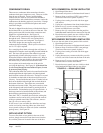
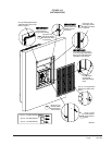
The wall sleeve is attached to the I-TEC unit from the
outside of the building. See Figures 11A & 11B. Refer
to wall sleeve Manual 2100-562 supplied with sleeve.
Following are the steps for attaching the I-TEC to the
wall sleeve.
1
. Lift the unit into place making sure that it is
aligned side to side.
2. Push the unit back until the rear panel touches the
sleeve gasket.
3. This unit must be level from side to side and from
front to back. If adjustments are necessary, shim
up under the base rails with sheets of metal or any
substance not affected by moisture.
4. Attach the sleeve to the unit using the ten (10)
¾"
long self-tapping screws supplied with the sleeve.
5.
The exhaust sleeve has three (3) ¾" long screw slots
in each side flange. Line these up with the screw
engagement holes in the fan panel. Attach using six
(6) ¾" long pointed sheet metal screws supplied
with the sleeve. Extend the sleeve out until it is
flush with the louver grill attachment angles.
6. Lock the sleeve in place using two (2)
½" long
pointed
sheet metal screws on each side by
shooting through the slot into a pre-punched hole.
7. A bottom trim piece is shipped loose for
installation beneath the doors. Attach the trim
piece to the unit with screws provided.
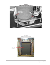
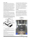
8. The compressor is secured to the base with two
(2) bolts for shipping. Both bolts are identified
with a tag. Remove shipping bolts (Figure 5).
WIRING – MAIN POWER
Refer to the unit rating plate and/or Table 2 for wire sizing
information and maximum fuse or “HACR Type” circuit
breaker size. Each unit is marked with a “Minimum Circuit
Ampacity”. This means that the field wiring used must be
sized to carry that amount of current. Depending on the
installed KW of electric heat, there may be two field power
circuits required. If this is the case, the unit serial plate will
so indicate. All models are suitable only for connection
with copper wire. Each unit and/or wiring diagram will be
marked “Use Copper Conductors Only suitable for at least
75°C”. THESE INSTRUCTIONS MUST BE
ADHERED TO. Refer to the National Electrical Code
(NEC) for complete current carrying capacity data on the
various insulation grades of wiring material. All wiring
must conform to NEC and all local codes.
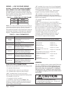
The electrical data lists fuse and wire sizes (75°C copper)
for all models, including the most commonly used heater
sizes. Also shown are the number of field power circuits
required for the various models with heaters.
The unit rating plate lists a “Maximum Time Delay
Relay Fuse” or “HACR Type” circuit breaker that is to
be used with the equipment. The correct size must be
used for proper circuit protection, and also to assure that
there will be no nuisance tripping due to the momentary
high starting current of the compressor motor.
See “START UP” section for information on three phase
scroll compressor start-ups.
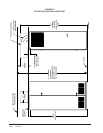
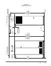
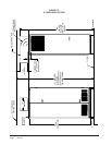
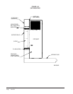
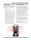
The field wiring conduit connections are located on the top
right-hand corner of the unit with a wire raceway to feed
the wires down to the circuit breaker(s). See Figure 12.
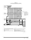
FIGURE 12
COMPONENT LOCATION
VENT OPTION
CONDENSER COIL
WIRE RACEWAY
COMPRESSOR
EVAPORATOR COIL
CONTROL PANEL
ELECTRIC HEAT
INDOOR BLOWER
OUTDOOR FAN
LOW VOLTAGE
REFRIGERANT PORT