


Installation and Wiring
5
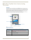
ENV-VST-C - Operation / Reference Guide
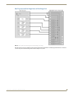
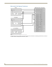
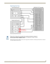
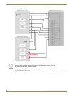
Wiring Terminals
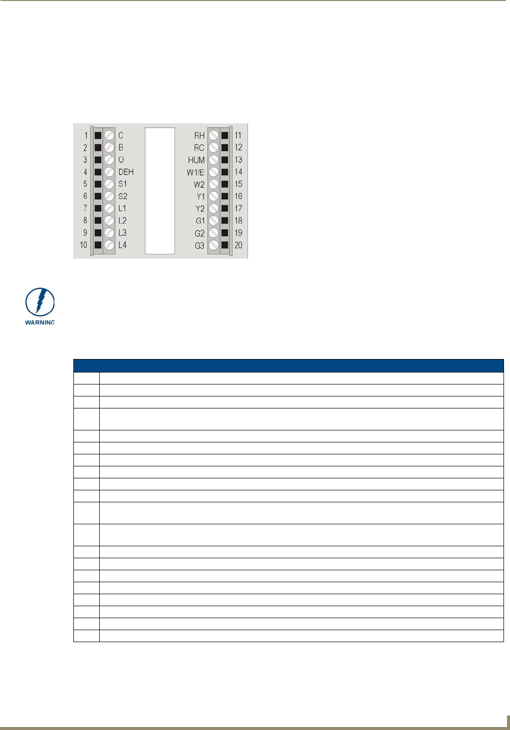
ViewStat Color Communicating Thermostats are equipped with terminals RC, RH, C, Y, W, G, O, B, S1, S2, L1, L2, L3,
and L4. You can use terminals S1 and S2 to accommodate a remote temperature sensor (see the Installing a Remote
Sensor section on page 14 for more information).
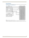
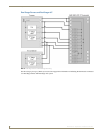
Terminals L1-L4 connect to the AxLink cable. The remaining terminals are used to control various types of heating and
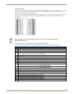
cooling systems detailed in the following sections. FIG. 2 displays the layout of the terminals on the thermostat’s
motherboard.
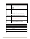
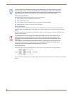
Communication and Equipment Terminal Wiring Definitions
The following table lists the communication and equipment terminal wiring definitions for the thermostat.
FIG. 2 Terminal layout
Applying voltage to the external temperature sensor pins (S1 and S2) can cause permanent
damage to the thermostat.
Communication and Equipment Terminal Wiring Definitions
RH 24 VAC in
RC 24 VAC in for AC relays. If a separate 24 VAC is not supplied to the RC terminal, install a jumper from RH to RC.
C 24 VAC common
G1 Fan on 1. If you are using a single speed fan, you should connect it to the G1 terminal, since the fan speed is set
to Low by default. On a multi-speed fan, G1 is the lowest speed.
G2 Fan on 2. On a multi-speed fan, G2 is the medium speed.
G3 Fan on 3. On a multi-speed fan, G3 is the highest speed.
W1 1st stage heat or emergency heat for a heat pump system.
W2 2nd stage heat
Y1 1st stage compressor
Y2 2nd stage compressor.
B Reversing valve (heat). Either the B or O relay will be connected to the reversing valve based on the type of
reversing valve used. Connect one or the other. DO NOT CONNECT BOTH.
O Reversing valve (cool). Either the B or O relay will be connected to the reversing valve based on the type of
reversing valve used. Connect one or the other. DO NOT CONNECT BOTH.
DEH Dehumidify
HUM Humidify
S1 External thermistor. The Color ViewStat supports only one external sensor.
S2 External thermistor. The Color ViewStat supports only one external sensor.
L1 AxLink PWR. This terminal is optional for AxLink connections.
L2 AxLink AxP. This terminal is required for AxLink connections.
L3 AxLink AxM. This terminal is required for AxLink connections.
L4 AxLink GND. This terminal is required for AxLink connections.