


Installation and Wiring
4
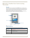
ENV-VST-C - Operation / Reference Guide
Removing the Faceplate from the Base
No tools are required to disassemble the thermostat - simply use your hands to pull the front panel off of the base.
Mounting the Base to a Wall
You should only mount the ViewStat Color Communicating Thermostat onto a sheetrock wall with the anchors and
screws provided with the unit. There are four screw holes located on the base of the thermostat.
1. Place the base over the wire hole opening in the wall. Level the base (leveling required for appearance only) and
mark the screw hole mounting locations.
2. Using the supplied wall anchors, drill 1/4" hole in the center of the marked locations, and tap the wall anchors into
the holes. If using the supplied screws only, drill a 3/32" hole in the center of the marked locations.
3. Fasten the base to the wall with the supplied screws.
4. Seal the wire entry with caulk, drywall putty, or insulation.
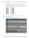
Wiring the Thermostat
1. Make sure the HVAC system power is off.
2. Strip 1/4" (0.63 cm) of insulation from each wire you are using.
3. Secure the wires into the terminals on the base according to the appropriate wiring diagram, as described below.
Refer to the Wiring Diagrams on page 7.
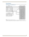
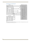
Single Stage Furnace and Single Stage A/C - Refer to the Single Stage Furnace and Single Stage A/C on
page 7.
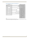
Dual Stage Furnace and Dual Stage A/C - Refer to the Dual Stage Furnace and Dual Stage A/C on page 8.
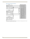
Roof Top Unit with Dual Stage Heat and Dual Stage Cool - Refer to the Roof Top Unit with Dual Stage
Heat and Dual Stage Cool on page 9.
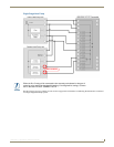
Boiler with A/C with Separate Transformers - Refer to the Boiler and A/C with Separate Transformers on
page 10.
Single Stage Heat Pump - Refer to the Single Stage Heat Pump on page 11.
Two Stage Heat Pump - Refer to the Two Stage Heat Pump on page 12.
First Stage Radiant Floor Heat, Second Stage Furnace One Stage of Cooling - Refer to the First Stage
Radiant Floor Heat, Second Stage Furnace with Single Stage Cooling on page 13.
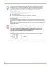
4. Check each wire to ensure it is securely fastened, not broken, and any exposed wires are not touching each other.
Loss of internal programs may result from static discharge to the thermostat circuit board. Touch a
grounded metal object to discharge any static charge before handling the circuit board.
Minimize the wire entry hole size and seal. Drafts from inside the wall could affect temperature
readings.
A qualified HVAC technician should perform these steps to ensure proper termination.
Use color-coding practices (i.e. white wire to W terminal) whenever possible.