


8
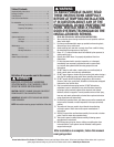
Please Do Not Return This Product To The Store. Contact your local Wayne-Dalton dealer. To find your local Wayne-Dalton dealer, refer to your local
yellow pages business listings or go to the Find a Dealer section online at www.Wayne-Dalton.com
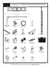
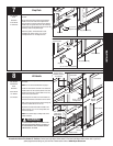
Tools Needed:
1
#1 End and center hinge
2
Hinges
Power Drill
7/16” Socket Driver
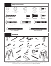
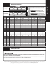
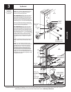
NOTE: Refer to the door section identification on page
5 to determine your lock (second), intermediate I
(third), intermediate II (fourth), intermediate III (fifth),
intermediate IV (sixth), intermediate V (seventh) and
top sections. Measure your sections to make sure
they are the correct height as indicated on the chart.
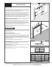
Locate the bottom section, using #1 hinges for the
end stiles and depending on the width of your door,
enough #1 hinge(s) for each of the center stile(s)
location.
NOTE: The #1 hinges serve as end hinges and center
hinges on the bottom section. The #1 hinges also
serve as center hinges at all center hinge locations.
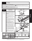
Place the hinges on the section so that the lower (#)
leaf of the hinge is over the pre-punched holes in
the #1 and #4 of the end stiles and the pre-punched
holes of the center stile(s) at the top of the section.
Secure the hinges to the section using (2) 1/4” - 14
x 7/8” self tapping screws for each, then insert the
roller into the appropriate end hinge tube.
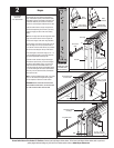
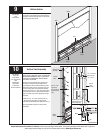
Repeat for all other sections using #2 end hinges
second section (lock section), or the #3 end hinges
third section (intermediate section), or the #4 end
hinges fourth section (intermediate section II), or
the #5 end hinges fifth section (intermediate section
III), or the #6 end hinges sixth section (intermediate
section IV), or the #7 seventh section (intermediate
section V) of the door.
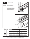
NOTE: If you have windload option codes 1124, 1125,
1142, or 1144: Double end hinges and long shaft
roller are required on each end of each section.
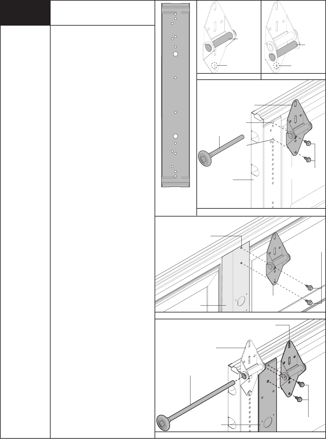
IMPORTANT: WHEN PLACING ROLLERS INTO END
HINGES NUMBER 2 AND HIGHER, THE ROLLER GOES
INTO TUBE FURTHEST AWAY FROM SECTION.
1
Roller
placement
Typical hinge
stamping location
Single end hinge
(2) 1/4”- 14 x 7/8”
Self drilling screws
End hinge
Short shaft
roller
End stile
#1
#4
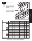
1
2
3
4
5
6
7
7
6
5
4
3
2
1
END STILE HOLE
PATTERN (LEFT SIDE
IS SHOWN. RIGHT
SIDE IS OPPOSITE.)
2
#2 Thru #7 End hinges
Roller
placement
Typical hinge
stamping location
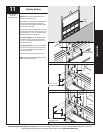
Center
hinge
(2) 1/4”- 14 x 7/8”
Self drilling screws
Center
stile
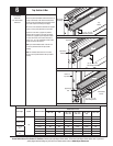
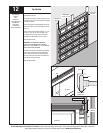
1
1
Previously installed
end hinge
Long shaft roller
End hinge
(2) 1/4”- 14 X 7/8”
Self drilling screws
Stile
Double end hinge
Center hinge
Pre-punched holes
in center stile