


13
Please Do Not Return This Product To The Store. Contact your local Wayne-Dalton dealer. To find your local Wayne-Dalton dealer, refer to your local
yellow pages business listings or go to the Find a Dealer section online at www.Wayne-Dalton.com
Tools Needed:
Tools Needed:
INSTALLATION
7
Lift handle inside
Lift handle outside
8
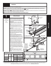
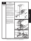
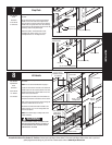
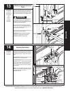
Lift Handle
NOTE: Doors with a keyed lock do not require this
lift handle.
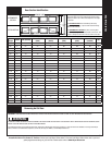
NOTE: For door section identification see page 5.
Locate the inside center most stile or the desired lift
handle location on the lock (2nd) section of the door.
Position the lower hole in the lift handle 4” from the
bottom of the second section.
Vertical align the lift handle, use the lift handle as a
template and mark the hole locations on the section.
Drill (2) 9/32” dia. holes through section. Enlarge the
holes from outside the door to 1/2” dia.
Assemble the outside and inside lift handle to the
section using (2) 1/4” x 2-1/2” carriage bolts and
nuts and (2) spacers.
NOTE: Do not drill through or enlarge holes on the
inside of the door.
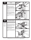
TO AVOID POSSIBLE INJURY, LIFT HANDLES THAT
ARE INSTALLED WITHIN 4 INCHES (102 MM) OF A
SECTION INTERFACE SHALL PROMOTE VERTICAL
ORIENTATION OF THE HAND.
Tape Measure
Pencil
Power Drill
9/32” Drill Bit
1/2” Drill Bit
7/16” Wrench
Lock section
Lock
section
Bottom
Section
Bottom section
Lift handle
Lift handle
(2) Spacers
(2) 1/4”-20
Hex nuts
(2) 1/4” x 2-1/2”
Carriage bolts
4”
Enlarge holes on
outside of section to
1/2” diameter.
9/32” Diameter
holes (do not
enlarge holes).
Pencil
Power Drill
5/16” Drill Bit
7/16” Wrench
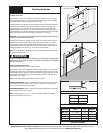
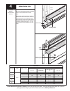
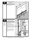
Step plate
Step Plate
Locate the center most stile of the bottom section of
the door.
On the inside of the door, center the step plate/lift
handle on the center most stile no higher than 8”
from the bottom of the door. Using the step plate/lift
handle holes as a guide, drill a 5/16” dia. hole along
each side of the stile through the face of the door. Be
extremely careful to keep drill straight.
Mount step plates / lift handles back to back,
straddling stile. Secure with (2) 1/4” x 2-3/4”
carriage bolts and 1/4”-20 flange hex nuts.
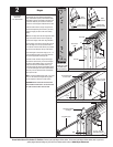
Inside step plate
Outside step plate
(2) 1/4”-20
Flange hex nuts
(2) 1/4 x 2-3/4” Carriage bolts
Step plate
Step plate assembly
Step plate assembly
Bottom section
Bottom section
Bottom section
8” Max mounting
height
8” Max mounting
height
Bottom section
Vertically
aligned
Lock Section
Bottom section
WARNING