


20
Please Do Not Return This Product To The Store. Contact your local Wayne-Dalton dealer. To find your local Wayne-Dalton dealer, refer to your local
yellow pages business listings or go to the Find a Dealer section online at www.Wayne-Dalton.com
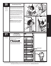
Tools Needed:
Tools Needed:
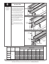
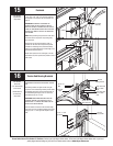
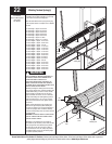
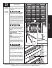
Align the stationary spring cone(s) with the holes in
the center bearing bracket. Secure the spring(s) to
the center bearing bracket with (2) 3/8”-16 x 1-1/2”
hex head bolts and 3/8”-16 nuts.
IMPORTANT: SPRINGS UNDER TENSION CAN BE
DANGEROUS.
IMPORTANT: THE SPRING WARNING TAG(S)
SUPPLIED MUST BE SECURELY ATTACHED TO THE
STATIONARY SPRING CONE IN PLAIN VIEW. SHOULD A
REPLACEMENT SPRING WARNING TAG BE REQUIRED,
CONTACT WAYNE-DALTON FOR FREE
REPLACEMENTS.
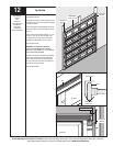
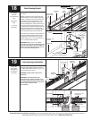
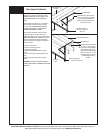
19
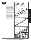
Torsion Spring(s) Installation
Torsion
spring
(1) 3/8”-16 x 1-1/2”
Hex head bolt
(1) 3/8”-16 Nut
(1) 3/8”-16 Nut
Center bearing bracket
Torsion
spring
Torsion spring
Center bearing
bracket
Spring warning tag
Stationary
spring cone
Stationary
spring cone
9/16” Socket
Ratchet Wrench
9/16” Wrench
Step Ladder
Torsion
spring
Center Bearing Bracket
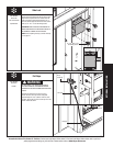
Power Drill
7/16” Socket Driver
Level
Tape Measure
Pencil
1/4” Torx Bit
Step Ladder
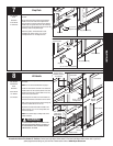
NOTE: For clarity the torsion counterbalance assembly
is not shown.
Measure to locate the center of the door and mark
a vertical pencil line on the mounting surface above
the door, to indicate the center line of the door. Then,
measure from the center of the bearing, in one of
the end bearing brackets, DOWN to the top of the
door. Using that dimension, measure UP from the top
of the door and mark a horizontal pencil line on the
mounting surface, intersecting the vertical pencil line.
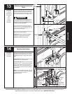
Now align the edge of the center bearing bracket
along the vertical pencil line on the mounting surface.
Center the bearing bracket on the horizontal line.
This will ensure the torsion tube is level between the
center and end bearing brackets. Attach the center
bearing bracket, in this location, to the mounting
surface, using (2) 5/16” x 1-5/8” lag screws and (1)
5/16” x 2” tamper-resistant lag screw.
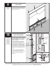
IMPORTANT: USE THE 5/16” X 1 5/8” TAMPER-
RESISTANT LAG SCREW ONLY IF MOUNTING SURFACE
MOUNTED OVER MASONRY. TAMPER-RESISTANT LAG
SCREW MUST BE ATTACHED THROUGH THE BOTTOM
HOLE OF THE CENTER BEARING BRACKET.
Vertical
line
Mounting surface
Equal
distance
Center of end
bearing bracket
Horizontal
line
Center bearing
bracket
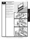
Mounting
surface
Horizontal line
Center bearing
bracket
(1) 5/16” x 1-5/8”
Lag screw
(1) 5/16” x 1-5/8”
Lag screw
Vertical
line
18
(1) 5/16” x 2”
Tamper-resistant lag screw or
(1) 5/16” x 1-5/8” lag screw
(1) 3/8”-16 x 1-1/2”
Hex head bolt