


7
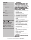
Please Do Not Return This Product To The Store. Contact your local Wayne-Dalton dealer. To find your local Wayne-Dalton dealer, refer to your local
yellow pages business listings or go to the Find a Dealer section online at www.Wayne-Dalton.com
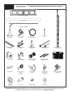
Tools Needed:
INSTALLATION
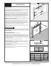
Begin the installation of the door by checking the opening. It must be the same size as the door. Vertical jambs must be plumb and level with header. Side clearance, from
edge of door to wall, must be a minimum of 3-1/2” (89mm) on each side.
IMPORTANT: STAINLESS STEEL OR PT 2000 COATED LAG SCREWS (NOT SUPPLIED) MUST BE USED WHEN INSTALLING CENTER BEARING BRACKETS, END BRACKETS, JAMB
BRACKETS, OPERATOR MOUNTING/SUPPORT BRACKETS AND DISCONNECT BRACKETS ON TREATED LUMBER (PRESERVATIVE-TREATED). STAINLESS STEEL OR PT 2000
COATED LAG SCREWS ARE NOT NECESSARY WHEN INSTALLING PRODUCTS ON UN-TREATED LUMBER.
IMPORTANT: WHEN INSTALLING 5/16” DIAMETER LAG SCREWS USING AN ELECTRIC DRILL/DRIVER, THE DRILL/DRIVER’S CLUTCH MUST BE SET TO DELIVER NO MORE THAN
200 IN. LBS. OF TORQUE. FASTENER FAILURE COULD OCCUR AT A HIGHER SETTING.
NOTE: It is recommended that 5/16” lag screws be pilot drilled using a 3/16” drill bit, prior to fastening.
NOTE: Use this manual in conjunction with the windload specification sheet provided with your door.
Installation
NOTE: For door section identification see page 5.
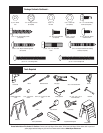
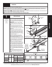
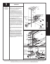
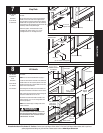
Uncoil the counterbalance cables and secure the
cable loop to the clevis pin and bottom bracket using
a 5/16” flat washer and cotter pin. Repeat for other
bottom bracket.
IMPORTANT: RIGHT AND LEFT HAND IS ALWAYS
DETERMINED FROM INSIDE THE GARAGE LOOKING
OUT.
Locate the bottom section, attach the left hand
bottom bracket to the end stile using (4) 1/4”-14
x 7/8” self drilling screws and (1) 1/4”-14 x 5/8”
tamper-resistant self drilling screw as shown. Repeat
for other side.
NOTE: All doors are provided with the tamper
resistant fastener for the bottom brackets. However,
the professional installer is most likely to have the
proper tool to install this fastener. If the homeowner
does not have the proper tool to install the tamper
resistant fastener, use a regular 1/4” - 14 x 7/8” self
drilling screw in its place.
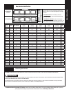
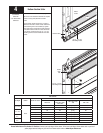
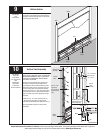
Refer to the u-bar schedule (bottom of page) to
determine if the bottom section requires a u-bar.
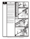
U-bar attachment (if required): Position the u-bar
over the bottom brackets and center the u-bar side
to side on the bottom section. Secure the u-bar to the
bottom section using (2) 1/4”-14 x 7/8” self drilling
screws at each end and center stile location(s).
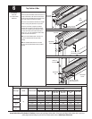
NOTE: If you have windload specification option
codes 1124, 1125, 1142 and 1144: Extension
brackets and long shaft rollers are required. Position
the extension bracket flush against the end stile and
slide it underneath the u-bar (if applicable). Align
the extension bracket with the bottom bracket by
inserting a long shaft roller with spacer through the
bottom bracket and extension bracket hinge tubes.
Attach the extension bracket to the endstile with (2)
1/4” - 14 x 7/8” self drilling screws as shown. Repeat
for other side.
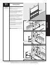
NOTE: Verify astragal (bottom seal) is aligned with
door section. If there is more than 1/2” excess
astragal on either side, trim astragal even with door
section.
1
Bottom Bracket
Power Drill
7/16” Socket Driver
Pliers
1/4” Torx bit
Clevis Pin
Counterbalance
cable
Left hand
bottom
bracket
Short or long
shaft roller
(only windload
option codes
1124/1125/1142
and 1144 use long
shaft rollers)
Spacer
Bottom
Bracket
Hinge tubes of
bottom bracket
Bottom
section
Hinge tube of
extension bracket
(if required)
U-bar (if required)
Stile
(2) 1/4”- 14 x 7/8”
Self drilling screws
Warning
label
Warning label
Bottom
bracket
End Stile
Washer
(2) 1/4”- 14 x 7/8”
Self drilling screws
(1) 1/4”- 14 x 7/8”
Self drilling or (1) 1/4”- 14 x 5/8”
tamper-resistant screw
Cotter Pin
(4) 1/4”- 14 x 7/8”
Self drilling screws
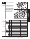
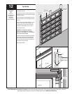
U-Bar Schedule
Door height Section
Position
on
section
Windload Option codes
1143/1144
1104/1123/1124/1125/
1141/1142
8’ 3” to 8’ 9”
Bottom Bottom
(1) Req. (1) Req.
9’ 0” to 10’ 6” NA (1) Req.
10’ 9” to 12’ 3” NA (1) Req.
12’ 6” to 14’ 0” NA (1) Req.
U-bar (if required)
Bottom section
Astragal