


9
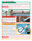
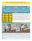
Step 5: Cable Drum Installation
NOTE: Do not remove shrink wrap from cable
drums until instructed to do so.
Cable drums are right and left. Be sure to check the
identifi cation on each drum to make sure the correct
drum is installed on its corresponding side.
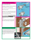
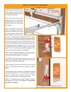
Apply grease to both sides and outer diameter of the
fl ange of the drum shaft.
Insert the 1/2-13 x 2” socket head cap screw into the
drum shaft. Then insert the screw and shaft into the
drum so that the screw threads and drum shaft are
showing out past the drum bearing.
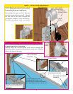
Install the drum/shaft/screw assembly into the 3/4”
hole in the fl ag bracket. Be sure the end of the shaft
is inserted into the hole in the fl ag angle.
Secure assembly with a 1/2” washer and 1/2”
lock nut.
Check to make sure the drum will rotate freely
on the shaft. If not, loosen 1/2” lock nut until the
drum is free to rotate. Repeat for opposite side.
CABLE DRUM
DRUM SHAFT
1/2-13 X 2” SOCKET
HEAD CAP SCREW
1/2-13 X 2” SOCKET
HEAD CAP SCREW
APPLY GREASE
TO DRUM SHAFT
FLANGE
DRUM ASSEMBLY
(SHRINK WRAPPED)
1/2” WASHER
1/2” LOCK
NUT
3/4” HOLE
FLAG
BRACKET
DRUM SHAFT
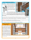
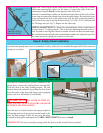
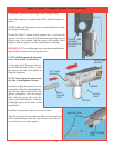
Locate the end of the lifting cable where the custom loop
was made earlier in the instructions. Carefully pull the
cable, bringing the loop to the milford pin located in the
bottom bracket on the edge of the bottom section. Secure
the cable loop around the milford pin, making
sure the loop is over the head of the milford pin
and around the smaller diameter. Repeat for the
other side.
LIFTING
CABLE
Step 6: Bottom Bracket Lifting Cables
MILFORD PIN ON
BOTTOM BRACKET