


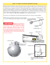
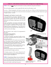
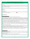
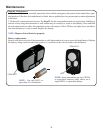

Step 27: Custom Settings
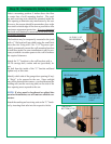
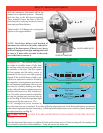
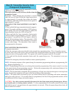
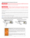
Step 26: Lock Arm Installation
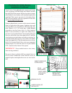
the detent pin CLOCKWISE in 1/4 turn increments. Operate the door to confi rm each adjustment. If the motor
pivots to soon, adjust detent pin again. Repeat procedure until motor pivots to full down position when the
26
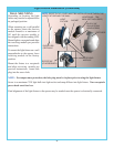
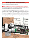
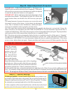
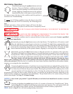
Step 25: Detent Adjustment (if required)
IMPORTANT! - FOR SYSTEM SECURITY: The motor is de-
signed to pivot down after the door closes completely. If the motor
does not pivot or pivots too soon, the detent may need to be adjusted
in order for the door lock feature to work properly.
IMPORTANT! Before making any detent pin adjustments, check
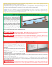
and adjust door balance. Door should not raise off of fl oor with
spring tension alone, nor should it free fall from any open posi-
tion.
The normal amount of pressure the opener uses to pivot the motor
downward is preset at the factory via the detent pin adjustment
screw. Due to variations in door installations, a detent pin adjust-
ment may be needed in order to properly pivot the motor.
A.) If the motor does not pivot down, or pivots down only partially, the detent pin is set too hard. Using a fl at
head screwdriver, turn the detent pin COUNTER CLOCKWISE in 1/4 turn increments. Operate the door to
confi rm each adjustment. If the motor does not pivot on door closing adjust detent pin again. Repeat procedure
until motor pivots to full down position when the door is completely closed.
B.) If the motor pivots down prematurely (before the door is completely closed) or if the motor is “slapping”
too aggressively against the top of the door, the detent pin is set too soft. Using a fl at head screwdriver, turn
DETENT PIN
Place the emergen-
cy disconnect in the
manual operated
position, motor will
pivot to the up posi-
tion. Insert the lock
arm into the motor
groove and align the
lock arm to the #4 hole.
Secure the lock arm to the motor with (1) M5 x 0.8 phillips
pan head screw. After assembly of the lock arm, manually
raise and lower the door and verify that the lock arm does
not interfere with the door. If there is interference between
the door and the lock arm, remove the pan head screw and align to the #3hole. Secure with the phillips pan head
screw. Try manually raising and lowering the door until there is clearance between the door and the lock arm.
NOTE: Do not operate the door if there is interference between the lock arm and the door. Reconnect the
1
3
2
4
LOCK
ARM
MOTOR
GROOVE
MOTOR
M5 X 0.8 PHILLIPS PAN HEAD SCREW
Custom pet position: Normal install routine sets the pet position to ap-
proximately eight inches above the ground. The pet opening height may be
changed to open anywhere between 8” and 30” above the ground. To change
the automatic pet opening height refer to the following procedure:
1. After completion of the normal install routine, with the door in the closed
position, place the disconnect handle in the manual operated position.
UP/DOWN
BUTTON
PET BUTTON