


20
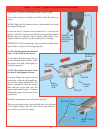
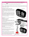
VIEW OF THE OPENER
FROM THE FRONT
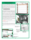
JUMPER INSTALLED
ON PINS “PE”
OPENER
SENDING IR LED
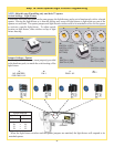
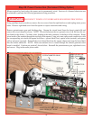
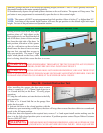
Uncoil wires from photoelectric sensors and route
wires up garage wall and along door header towards
the right side of the opener
.
Route wires above torque
tube and tack wires in place with insulated staples (not
supplied). Take care to run wires in a location where
they will not interfere with the operation of the door
and do not staple through wire.
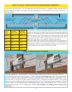
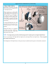
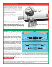
Connect photoelectric sensors to the opener terminal
block in right side of the opener. Separate wire ends
and strip about 1/2” of insulation off each of the wire
ends. Insert a 3/32” (2,5 mm) max. width fl athead
screwdriver into the lower hole #1 of the terminal
block. Twist screwdriver to open wire clamp in up-
per hole #1 of terminal block. Insert both sender and
receiver solid white wires into upper hole #1 until the
wires bottom out and release screwdriver tension. In-
sert both sender and receiver wires (white with black
strip) into upper hole #2 by the same process on lower
hole #2 of terminal block. Once wires are connected
install jumper on to the left most set of pins labeled
“PE”, located on the front of the opener.
IMPORTANT! Keep sender/receiver wires away
from moving members.
Be sure to observe polarity. Pull on external wires to
test for secure connection. Check that the wires are
stapled in place and staples have not cut wire insula-
tion.
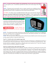
INSERT SENDER
WIRES
INSERT
RECEIVER
WIRES
WIRE ROUTING
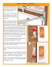
Photoelectric Safety Sensor
Installation Continued
INSERT WIRES INTO
UPPER HOLES
RIGHT HAND SIDE
VIEW OF OPENER
INSERT SCREW-
DRIVER INTO
LOWER HOLES
SOLID
WHITE WIRES
WHITE WIRES
WITH BLACK
STRIPES