


7
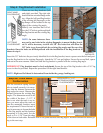
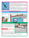
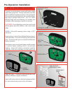
Step 3: Lifting Cable Loop
Extension idrive™ Installation
idrive™ Retro-fi t Installation
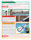
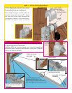
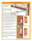
Step 2: Remove Front Sheave
Disassemble the existing front cable sheaves. Typi-
cally the front sheave is secured with a bolt and nut to
the horizontal angle. Repeat for other side. (NOTE:
It may be helpful to refer to the original garage
door’s owner’s manual for removing parts from
the original door.)
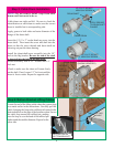
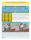
Step 1: Extension Spring Relief
Raise the door to the fully open position and clamp locking pliers to the back legs of both vertical tracks, below
the bottom rollers to prevent the door from falling (see Fig. 1). By opening the door, you release most of the
spring tension. Carefully unfasten the S-hook from the horizontal angle. Remove the counterbalance cable.
Leave extension spring with it’s sheave installed. Repeat for the other side.
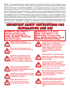
WARNING COUNTERBALANCE SPRING TENSION MUST BE RELIEVED BEFORE RE-
MOVING ANY HARDWARE. A POWERFUL SPRING RELEASING IT’S ENERGY SUDDENLY CAN
CAUSE SEVERE, EVEN FATAL INJURY.
NOTE: Only remove springs when door is in the up position and visegrip pliers are attached to the
track.
LOCKING
PLIERS
Locate the bottom bracket at the lower edge of the bottom
section. The lift cable will be attached to the brackets
milford pin. Measure the diameter of the head of the pin
and record the measurement. Locate the drum assemblies
provided with the kit. They will have a cable attached
with a loop formed on the end of the cable.
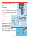
Locate the cable loop tool and install the loop over the
shape that corresponds to the milford pin head size you
measured. Use the larger size if the milford pin head size
is greater than or equal to 1/2”, and the smaller size if the
diameter is less than 1/2”. With the cable installed onto
the tool, pull the cable tight, forming it around the loop
tool. Remove the cable from the tool while holding the
cable so it does not slip in the crimp sleeve. Place the
crimp sleeve on a hard surface and using a hammer, hit
the crimp sleeve until it is squeezed tightly around the cable. Verify the loop has been set securely by pulling
on the loop. Repeat for the other cable. Set the drum/cable assemblies aside until needed.
WARNING FAILURE TO CRIMP SLEEVE SECURELY TO CABLE, CAN CAUSE CABLE
TO SLIP OUT, ALLOWING DOOR TO FALL DURING OPERATION, RESULTING IN SEVERE OR
FATAL INJURY.
LOOP
TOOL
CRIMP SLEEVE
PULL LIFTING CABLE
TIGHT SNUGGING THE
CABLE TO SIZE AROUND
THE FIXTURE
MILFORD PIN
BOTTOM
BRACKET
CAREFULLY REMOVE THE “S” HOOK AND COUNTERBALANCE
CABLE (REPEAT FOR THE OTHER SIDE)
ATTACH LOCKING PLIERS TO BACK LEG OF
TRACK BELOW ROLLER (BOTH SIDES)
FRONT CABLE
SHEAVE
HORIZONTAL
ANGLE
BOTTOM DOOR
SECTION
NUT
SAFETY
CABLE
(LEAVE IN-
STALLED)
BOTTOM
ROLLER
FIG. 1