


22
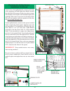
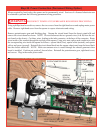
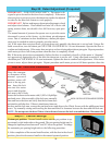
Where required by local codes, the opener can be permanently wired. Services of a licensed electrician can
be obtained to perform the following permanent wiring procedure.
WARNING DISCONNECT POWER AT FUSE/BREAKER BOX BEFORE PROCEEDING.
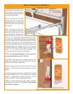
Using a phillips head screwdriver, remove the two screws from the right hand cover and unplug motor power
cable. Remove right hand cover from the opener to expose electronics and wiring.
Remove potentiometer gear and fi nishing plug. Unsnap the circuit board from the chassis stand-offs and
remove the circuit board as shown. NOTE: Do not disconnect the two ground wires (A & B) from the cir-
cuit board or the chassis. Cut three wires, leading to the inlet connector, at the base of the connector. Route
wires inside of the conduit through the top hole in the opener Using wire nuts, splice each conduit wire with
the corresponding wire inside the opener as follows: opener black (line), opener white (neutral), and opener
yellow and green (ground). Reinstall the circuit board back into the opener chassis and snap the board back
into the chassis stand-offs. NOTE: Make sure antenna wire is routed through the chassis grommet when
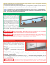
board is installed. Confi rm pot position* shown below. Reinstall the potentiometer gear, right hand cover,
and screws. Plug in the motor power cable.
Step 20: Power Connection (Permanent Wiring Option)
*POSITION POT NUT 1/16” - 1/8”
AWAY FROM LEFT STOP
ANTENNA
POTENTIOMETER GEAR
REMOVE AND DIS-
CARD FINISHING
PLUG
CHASSIS
STAND-
OFF
CUT
WIRES
HERE
GREEN &
YELLOW
(GROUND)
“A”
“B”
GROMMET
WHITE
(NEUTRAL)
BLACK
(LIVE)
INLET
CONNECTOR
*POTENTIOMETER
GEAR CLIP