PTAC-SVX01C-EN 9
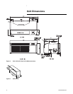
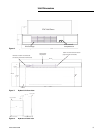
Unit Dimensions
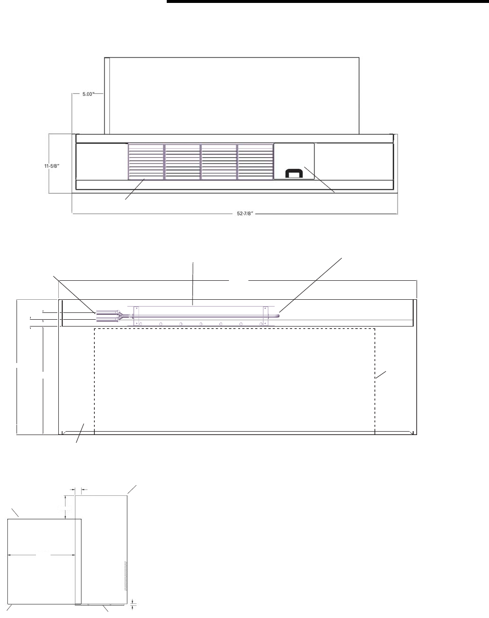
Figure 6. Top view of the hydronic kit
Figure 7. Hydronic kit front view
Figure 8. Hydronic kit side view
PTAC Wall Sleeve
Air discharge
Unit controls
compartment
1“
20-1/4”
16-1/5”
1-1/20”
53-2/3”
PTAC
Air inlet
Steam inlet and outlet connection
(right hand coil connection)
Steam/water
coil position
Hotwater or steam inlet and outlet
connection (left hand coil connection)
Front View
12.62
5.00”
1-3/8” - 1-1/2”
Top of wall sleeve
Hydronic front
Toe plate 0 to 3.0” long
Bottom of wall sleeve


