


16 PTAC-SVX01C-EN
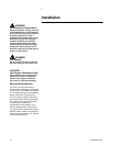
Installation
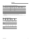
Notes: EN = Enabled - operations based on
other logic
Notes: N/C = No change from prior state
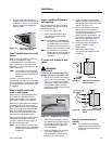
Step 8. Configure the display
module settings
Indoor Temperature setpoint
The indoor temperature setpoint
buttons tell the unit how warm or
cool the occupant wants the room.
The setpoint is set by pressinging the
up/down buttons on the interface
module. These buttons do not scroll
(i.e. holding the button will not
continue to adjust the setpoint value)
because each adjustment of the
setpoint value requires its own
unique button press.
Default setpoint on first power up:
72°F (22.0°C – closest approximation)
Setpoint resolution: ± 1°F (± 0.5°C)
User Mode Selection
Pressing the MODE button on the
unit tells the unit which mode the
occupant prefers. There are four
modes to choose from.
1. COOL
2. HEAT
3. FAN (fan only)
4. OFF (default for first power up)
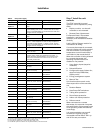
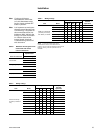
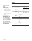
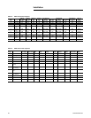
Table 8. Output settings
User Mode / Model
ID
Fan
High
ID
Fan
Low
Aux
Heat Comp
Rev
Valve
(PTHE)
OD
Fan
Rmt
Fan
Cond
Pump
(PTHE)
Vent
Door
/Fan
High Heat Pump
(PTHE only)
ON OFF OFF ON OF ON EN EN EN
Low Heat Pump
(PTHE only)
OFF ON OFF ON OFF ON EN EN EN
High Emergency/
Auxiliary Heat
ON OFF ON OFF N/C OFF EN EN EN
Low Emergency/
Auxiliary Heat
OFF ON ON OFF N/C OFF EN EN EN
High Cooling ON OFF OFF ON ON ON EN EN EN
Low Cooling OFF ON OFF ON ON ON EN EN EN
High Fan ON OFF OFF OFF N/C OFF EN EN EN
Low Fan OFF ON OFF OFF N/C OFF EN EN EN
Off OFF OFF OFF OFF N/C OFF OFF EN OFF
Fan Speed Selection
Pressing the FAN button on the
interface module determines fan
speed. There are two fan speeds to
choose from.
1. LOW (default for first power up)
2. HIGH
Field commissioning support
Manual Test Mode
A manual test mode is provided to
allow a field technician to verify
proper output and end device
operation through a predetermined,
timed sequence.
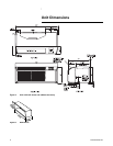
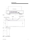
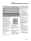
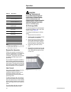
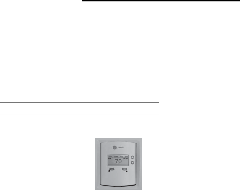
Figure 16. Digital display module
Fan
Mode
The sequence will automatically
advance through all outputs and exit
when the sequence has completed; it
is left to the technician to monitor the
status of the end devices during the
test to verify that each operates
properly.
Manual test is initiated by combining
the following conditions:
• User Mode = OFF
• Press and hold MODE &
SETPOINT DOWN for 5 seconds
During the test process, the word
"STEP" and the corresponding step
number will be lighted on the
display. After the final step has been
executed, the controller will exit
Manual test and force the controller
to into a reset.
Manual test mode may be cancelled
by pressing any button on the
display.
Manual test is not available if there is
no interface module, as is in Class 2
control applications.
The test sequence attempts to clear
unit diagnostics and restore normal
unit operation prior to testing the
outputs. If the diagnostics remain
after an attempt to clear them,
manual test may be affected or
disallowed.
Dehumidification
The PTAC controller does not directly
measure room humidity.
The PTAC provides dehumidfication
by combining the following actions
in a predefined sequence.
1. The PTAC subcools the room to a
preset state, a dehumidification
offset below the cooling setpoint.
2. The unit will automatically adjust
the fan speed.
3. When incorporating the vent
door option, the controller will
automatically adjust its position.