


PTAC-SVX01C-EN 35
Maintenance
Cooling Performance Test
Thermometers
The following precautions are
necessary in observing the
thermometer readings in the cooling
performance test.
1. Use two accurately calibrated
refrigeration type thermometers
or a thermocouple
potentiometer.
2. Thermometers are affected by
body heat or changes in airflow.
Therefore, secure the
thermometers in proper
locations with masking tape,
wire, or other applicable
retainers.
3. Observe readings without
touching or moving the
thermometers.
Sling Psychrometer
Use a sling psychrometer to obtain
the wet-bulb temperature and
determine the percent relative
humidity.
To obtain the wet-bulb, follow this
procedure using the sling
psychrometer.
• Saturate the wick (only once
during procedure of obtaining
wet-bulb readings) with clean
water slightly below room
temperature.
• Obtain the psychrometer reading
five to six feet in front of the unit
and approximately four feet off
the floor.
Note: Direct discharge airflow away
from the sling psychrometer.
Do not perform the cooling
performance test when the outside
temperature is 20°F below the room
temperature. For best results,
perform the test under peak load
conditions.
The air conditioner must operate at
least 20 minutes on the HIGH COOL
position before testing.
Cooling Performance Test
Record the following temperatures
for the cooling performance test:
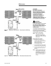
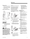
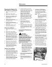
• Dry-bulb temperature of return
air at conditioner. Locate
thermometer as illustrated on
previous page.
• Dry-bulb temperature of
discharge air. Locate the
thermometer as illustrated on
previous page.
• The dry-bulb thermometer
temperature on the sling
psychrometer should be plus or
minus 1°F within reading
obtained on thermometer in the
return air. Check wet-bulb
temperature on sling
psychrometer and record same.
• After recording the wet-bulb
temperature, dry- bulb
temperature, and return air
temperature, calculate the
temperature difference as
follows.
• Subtract temperature obtained in
Step B from temperature
obtained in Step A. Use the
remainder temperature to
calculate from the cooling
change of temperature in the
Maintenance general
information section.
Example: Assume a PTHE1501 unit is
under test and the temperature
readings indicated below were
obtained.
1. Return air dry-bulb temperature:
80°F, Step A.
2. Discharge air dry-bulb
temperature: 69°F, Step B.
3. Return air, wet and dry-bulb
temperature as recorded in Step
C: dry- bulb 80°F, wet-bulb 75°F.
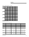
4. In left hand column of cooling
capacity charge headed dry-bulb,
find the 80° value in Table 20,
p. 25.
5. In column headed wet-bulb find
the 75° value and find the value
"8 -13" in the cooling range
column under model
“PTHE1501”.
This data shows the temperature of
the air passing through the cooling
coil is reduced at least 8°F but not
more than 13°F. This example unit is
operating normally for the existing
conditions.
For the example unit under test, the
temperature difference was 11°F
(80°F, return air, minimum 69°F
discharge air). Because the value is
within the listed cooling range 8 - 13,
this unit is considered to be
operating normally.
Note: Never test operation without
the unit in the wall sleeve. A
serious change in design
specifications for air
movement through the
evaporator and condenser
compartments, causing the
fan motor to over heat and
the refrigeration system to
become unbalanced will
occur when the unit is not
installed in the wall sleeve.
Electric Heat Test
For the electric heat test, the
following readings must be recorded
after the unit is interconnected with a
wattmeter or by recording the total
amp draw to the unit.
Note: The cabinet front must be in
place during this test.
• Record supply voltage to unit.
• Operate unit in highest heat
setting.
• Record wattage recorded on
wattmeter or total amp draw to
unit.
• Refer to the electric heat capacity
and electrical data section
(whichever is applicable for
voltage rating on the unit being
tested.)
• The total watts or amps recorded
should fall with in the minimum
and maximum watts/amps listed
on these charts
Example: Assume that a PTHE1501
230/208V with 3.5 kW electric heater
is under test.
1. Supply voltage as recorded -
208V.
2. Watts recorded -2750W or amps
recorded - 13.5 amps.