


40 PTAC-SVX01C-EN
Maintenance
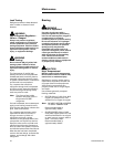
Removing the Outdoor Coil
and Outdoor Air Thermistors
1. Remove the chassis from the
wall.
2. Remove the front cabinet.
3. Remove the control box cover.
4. Disconnect the outdoor coil/air
thermistor wiring from the
control board.
5. Gently pull outdoor coil
thermistor from the bracket near
the capillary tube.
6. Gently remove outdoor air
thermistor which is located at the
drain valve.
7. Remove the outdoor coil/air
thermistor from the unit.
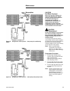
Indoor Fan and Motor
1. Remove the chassis from the
wall.
2. Remove the front cabinet.
3. Remove the heater/discharge
deck assembly. (Refer to the
heater disassembly instructions)
4. Remove the control box cover.
Disconnect the control wiring.
Remove the control box. Refer to
the power cord disassembling
for instructions on
disassembling the control box.
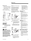
5. Remove the indoor fan motor
bracket screws (3) as shown.
6. Remove the set screw (you will
need a long Allen wrench)
securing the indoor fan to the
motor shaft and remove the
indoor fan and motor.
Outdoor Fan and Motor
1. Follow the directions for
removing the condenser except
don’t braze or remove the tubing
connecting to the condenser.
Capturing the system refrigerant
is also not necessary.
2. Remove the screw on the right
side of the unit (If you are
looking at the back of the PTAC)
toward the bottom of the PTAC
near the lip of the basepan.
3. Lift the condenser up and over
the lip of the basepan and move
just enough to gain access to the
outdoor fan and motor. Be
careful not to damage the
bottom of the condenser by
sitting it on the lip of the
basepan. Also, use caution when
bending the condenser to gain
access to the outdoor fan and
motor. The tubing is very fragile
and must be treated with care.
4. Remove the fan.
5. Remove the fan motor by
removing the two screws
securing it to the fan motor
bracket.
6. Disconnect the fan motor wiring
from the control by removing the
wire junction box cover on the
partition panel above the control
panel cover.
Control Board Replacement
Procedure
WARNING
Hazardous Voltage!
Disconnect all electric power,
including remote disconnects before
servicing. Follow proper lockout/
tagout procedures to ensure the
power can not be inadvertently
energized. Failure to disconnect
power before servicing could result
in death or serious injury.
Note: Before replacing the whole
control board, make sure that
the control board’s fuse is still
functioning. The specs for
the control board fuse are:
5X20mm, 250V, 315mA, fast
acting. For more information
on a blown fuse on the
Control Board, check the
Troubleshooting section of
this document.
1. Remove plastic cabinet front and
the metal cover that encloses the
control board
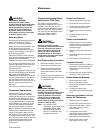
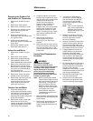
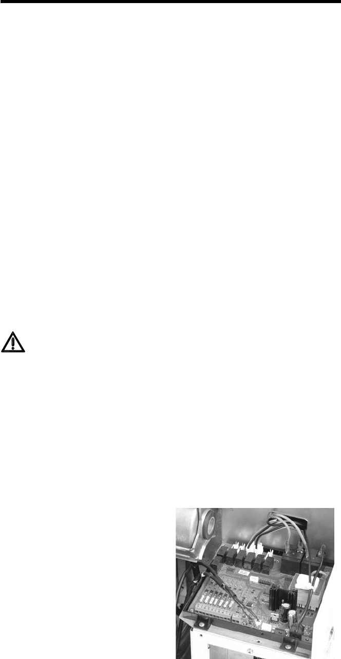
2. Remove the replacement board
from its package and set the
power jumper to match the unit
voltage .
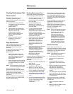
3. There are two different pin
connections, one for 230/208
VAC and another for 265 VAC .
The jumper for the 115 VAC
board is pre-installed in the P8
to P9 position.
Note: This is a very important
step, and it might lead to
damage of the control
board if the jumper is not
properly set.
4. Remove connections from the
existing control board, tagging
wires as required to ensure
correct re-assembly.
5. Remove 2 screws from the front
plastic mounting ears. Remove
the screw from the green wire
ground. Slide plastic chassis and
board back and lift out of place.
6. Engage catches on bottom of
plastic chassis of replacement
assembly with sheet metal
control box and slide forward to
lock in position. Re-install two
screws through the front plastic
mounting ears. Re-install green
ground wire.
7. Re-connect the wiring harness to
the new assembly in the same
positions that they were before
removal. This includes
temperature thermistors, as well
as the thermostats, zone sensors
and energy management.
8. Reinstall the sheet metal cover
over the control board.
9. Position the front cabinet over
the chassis and push the sides
until the retaining clips engage.
Figure 28. Power jumper