


PTAC-SVX01C-EN 39
Maintenance
WARNING
Hazardous Voltage!
Disconnect all electric power,
including remote disconnects before
servicing. Follow proper lockout/
tagout procedures to ensure the
power can not be inadvertently
energized. Failure to disconnect
power before servicing could result
in death or serious injury.
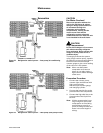
Reversing Valve
Occasionally the reversing valve may
stick in the heating or cooling
position or in the mid-operation.
When stuck in the mid-position, part
of the discharge gas from the
compressor is directed back to the
suction side resulting in excessively
high suction pressure.
Check the operation of the valve by
starting the system and switching the
operation from COOLING to
HEATING and then back to COOLING.
If no voltage is registered to the coil,
check the operation of the reversing
relay and the continuity of the
connecting wires.
If voltage is registered at the coil, tap
the valve body lightly while switching
the system from HEATING to
COOLING etc. If this fails to cause the
valve to switch position, remove the
coil connector cap and wiring and
test the continuity of the valve coil. If
the coil does not test continuous
replace it.
If the valve is inoperative, replace.
Component Replacement
Replacement of the compressor,
evaporator, condenser, capillary
tubes and reversing valve must be in
accordance with accepted service
practices. These procedures include
a complete evacuation of both high
and low sides, and changing of the
capillary tube assembly whenever
the refrigerant system is opened.
Before replacing a component in the
sealed system, make sure that the
cause for complaint does not lie in
the electrical circuit, control, overload
or is due to some other reason. The
serviceman must be familiar with the
operational characteristics of the
product and should not jump to
conclusions.
Temperature-Actuated Drain
Valve (model PTHE Only)
The PTHE is equipped with a
temperature-actuated drain valve
located in the base pan. As the
outdoor ambient decreases to 55°F,
the drain valve will begin to open.
The valve will be completely open
when the outdoor ambient
temperature falls to 50°F.
WARNING
Hazardous Voltage!
Disconnect all electric power,
including remote disconnects before
servicing. Follow proper lockout/
tagout procedures to ensure the
power can not be inadvertently
energized. Failure to disconnect
power before servicing could result
in death or serious injury.
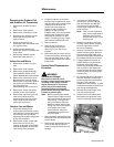
Unit Disassembly Procedures
1. Disconnect power to the unit.
2. Remove the unit front cover.
3. Remove the three screws on
each side of the chassis that
secure the chassis to the wall
sleeve.
4. Carefully slide the chassis out of
the wall sleeve and place on floor
or a protected cart.
WARNING
Hazardous Voltage!
Disconnect all electric power,
including remote disconnects before
servicing. Follow proper lockout/
tagout procedures to ensure the
power can not be inadvertently
energized. Failure to disconnect
power before servicing could result
in death or serious injury.
Note: ALL phases of this
installation must comply with
NATIONAL, STATE AND
LOCAL CODES. Improper
wiring or installation may
damage thermostat.
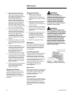
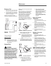
Power Cord Removal
1. Disconnect power to the unit.
2. Remove the unit front cover.
3. Remove two screws of power
cord connector front cover.
4. Remove the power cord strain
relief.
5. Remove power cord from
connector.
Power cord Installation
1. Install power cord to connector.
Gently press the connector into
position until top and bottom
latches engage.
2. Reinstall the power cord strain
relief.
3. Reinstall power cord connector
front cover.
4. Reinstall the unit front cover.
Capacitor Removal
1. Remove the control box. Refer to
the power cord disassembly for
instructions on removing the
control box.
2. Remove the screw securing the
capacitor to the control box.
Heater Assembly Removal
1. Remove the strain relief.
2. Remove the three screws
securing the discharge screen to
the chassis.
3. Unplug the power cord
connector and remove the power
cord.
Removing the Indoor Coil and
Indoor Air Thermistors
1. Remove the front cabinet.
2. Remove the control box cover.
3. Disconnect the indoor coil/air
thermistor wiring from the
control board.
4. Locate the indoor coil/air
thermistor on the suction tube or
evaporator. Gently pull the
thermistor from the housing.
5. Remove the indoor coil/air
thermistor from the unit.