PTAC-SVX01C-EN 43
Troubleshooting
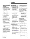
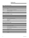
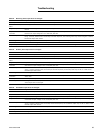
Table 34. Reversing valve output does not energize
Random restart timer Explanation
Power up control wait All controller outputs remain off until the timer expires.
Selected mode OFF, FAN
ONLY
Reversing valve held in current state because compressor use is not allowed.
Diagnostic present A specific list of diagnostics affects compressor operation. For more information, see the Diagnostics section in the
manual.
No power to the
controller
If the controller does not have power, the reversing valve does not operate. For the controller to operate normally, it
must have an input voltage of 115 or 208-230, 265 VAC.
Manual output test The controller includes a manual output test sequence you can use to verify output operation and associated output
wiring. However, based on the current step in the test sequence, the reversing valve may not be energized. Refer to
the Manual Output Test section.
Unit wiring The wiring between the controller output and the reversing valve must be present and correct for normal operation.
Normal operation PTHE unit is in heating mode.
Diagnostic present A specific list of diagnostics affects unit operation. For more information, see the Diagnostics section in the manual.
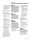
Table 35. Auxiliary heat output does not energize
Probable cause Explanation
Random restart timer All controller outputs remain off until the timer expires.
Selected mode OFF When off is selected at the display to the controller, the unit controls all outputs off.
Selected mode FAN
ONLY
When fan only is selected at the display to the controller, the unit only allows the indoor fan to energize.
Diagnostic present A specific list of diagnostics affects unit operation. For more information, see the Diagnostics section in the manual.
No power to the
controller
If the controller does not have power, the compressor does not operate. For the controller to operate normally, it
must have an input voltage of 115 or 230/208, 265 VAC.
Manual output test The controller includes a manual output test sequence you can use to verify output operation and associated output
wiring. However, based on the current step in the test sequence, the auxiliary heat may not be on. Refer to the
Manual Output Test section.
Unit wiring The wiring between the controller output and the auxiliary heat must be present and correct for normal operation.
Indoor Coil Freeze
protection
The compressor has been turned off because the indoor coil temperature has fallen below 35°F and has not risen
above 50°F.
Normal operation Auxiliary heat may not be needed to meet the load conditions see the section dealing with Auxiliary Heat Control.
Defrost Cycle During the active defrost cycle the auxiliary heat is controlled off. See the section on defrost control. Reversing
Valve output does not energize.
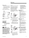
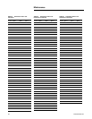
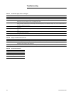
Table 36. Ventilation output does not energize
Probable cause Explanation
Random restart timer All controller outputs remain off until the timer expires.
Selected mode OFF When off is selected at the display to the controller, the unit controls all outputs off.
Diagnostic present A specific list of diagnostics affects unit operation. For more information, see the Diagnostics section in the manual.
No power to controller If the controller does not have power, the compressor does not operate. For the controller to operate normally, it
must have an input voltage of 115 or 230/208, 265 VAC.
Manual output test The controller includes a manual output test sequence you can use to verify output operation and associated output
wiring. However, based on the current step in the test sequence, the ventilation output may not be on. Refer to the
Manual Output Test section.
Unit wiring The wiring between the controller output and the ventilation must be present and correct for normal operation.
Normal operation See the section on Ventilation operation.
Defrost Cycle During the active defrost cycle the outdoor fan is controlled off. See the section on defrost control.


