18 PTAC-SVX01C-EN
Installation
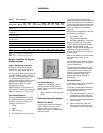
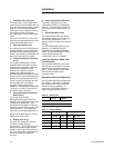
1. Ventilation Door Function
The power door works based upon
control logic functions. When the unit
is on, the vent door will open to allow
fresh air to be conditioned before
entering the room. When the unit is
off, the door closes to prevent
unconditioned air from entering the
room.
For more information on vent door
function with dehumidificaiton, refer
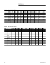
to the dehumidification chart.
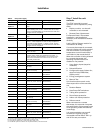
2. Indoor Fan Cycle set up
The indoor fan can be configured to
provide different types of operation
between its OFF and ON (high/low)
states. This setting is adjustable and
does not force the unit to reset.
3. Temperature Setpoint Limiting
set up
The range of temperature control
setpoints can be limited using this
configuration parameter. After the
controller has determined the
desired user setpoint from the
display, the resulting value is
validated against the setpoint limits.
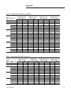
There are four valid combinations of
heating and cooling setpoint limits:
These set point limits apply to both
the occupied and unoccupied
standby, heating and cooling
setpoints. This setting is adjustable
“on-the-fly” and will not force the
unit into a restart condition.
4. Energy Management Setpoint
Offset set up
The range of the Energy
Management System's effect on
setpoints can be adjusted using this
configuration parameter. This
parameter is adjustable "on-the-fly"
and will not force the controller into a
restart condition. The range and
resolution of available selections is
Range: 0°F to 20°F( 0.0°C to 11.0°C)
Resolution: 1.0°F( 0.5°C)
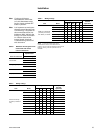
5. Display Unit set up
The user can change the way the
interface module displays
temperature. The symbols °F and °C
will not be present on the display;
however, the range and precision of
the room temperature and setpoint
values will make the selection
obvious.
6. Indoor temperature calibration
The indoor temperature can be
calibrated to match an independent
reading. The adjustment range is +/-
10.0°F (6°C) with a resolution of 1°F
(0.5°C).
7. Dehumidification Offset
The offset defines the point below
the setpoint where the unit will stop
running the compressor. A DH
display module is required to use this
feature.
The PTAC allows the options of 0°F
(disable), 1°F (default) and 2°F
(optional) for the dehumidification
offset. The dehumidification feature
will be disabled when the
configuration of 0°F is selected.
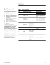
Last User Setpoint, Mode, and
Fan Selections
The controller saves the last inputs
that the user has chosen 5 seconds
after the user has ceased changing
them. These settings will be used
after the next power cycle or
controller reset.
Operation without configuration
The controller tests the configuration
for validity. If the data is corrupted
the controller will revert to default
values for every parameter. A
diagnostic code will be displayed
when using the default values.
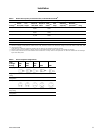
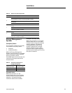
Table 10. Display units
Selection
#
Unit of
Measure
Display
Example
0 IP (English) 77 (DEFAULT)
1SI (Metric)24.5
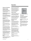
Table 11. Setpoint limiting
Cooling Setpoint Heating Setpoint
Selection
#Low Limit
High
Limit
Low
Limit High Limit
0 50°F 90°F 50°F 90°F (DEFAULT)
1 55°F 90°F 50°F 85°F
2 60°F 90°F 50°F 80°F
3 65°F 90°F 50°F 75°F


