


22 PTAC-SVX01C-EN
Operation
Notes:
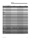
1. Connection to R enables input functions W, Y,
GL, GH, O,VT, and/or EN.
2. Connect 24VAC, 3VA maximum Remote Fan
Control Relay to RF and C
Remote Fan Operation
PTACs can operate a remote fan to
provide conditioned air to additional
rooms or areas that are not well
ventilated. The remote fan operates
any time the PTAC indoor fan is
operating.
The remote fan requires a 24 VAC, 3
VA maximum relay that connects to
the control board RF and C terminal
user inputs. The relay and remote fan
are field supplied. Refer to the wiring
diagrams section for wiring details.
Vent Control
Vent control draws fresh air into the
conditioned area to provide
ventilation when the indoor fan is
operating. However, this may
increase heating cooling loads and
operating costs.
To obtain access to the vent control,
remove the cabinet front and locate
the vent control lever on the left side
of the chassis. Push the vent control
lever up to open the vent or down to
close.
The unit ships with the vent door
closed and secured by a screw.
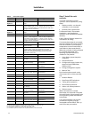
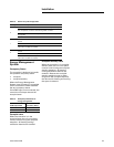
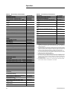
Table 16. User inputs
Input Function
TB1
+Remote display
communications link (+)
-Remote display
communications link (-)
TB2
EN Energy management
system input
VT Ventilation input
O Reversing valve (class 2
thermostat)
GL Low fan speed (class 2
thermostat)
GH High speed fan (class 2
thermostat)
Y Cool (class 2 thermostat)
W Heat (class 2 thermostat)
R 24VAC common1
C Ground2
RF Remote fan relay output
CAUTION
Freezing Temperatures!
Do not allow liquid refrigerant to
contact skin. If it does, treat the
injury similar to frostbite. Slowly
warm the affected area with
lukewarm water and seek immediate
medical attention. Direct contact
with liquid refrigerant may cause
minor or moderate injury.
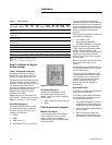
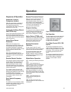
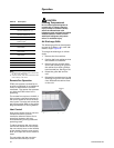
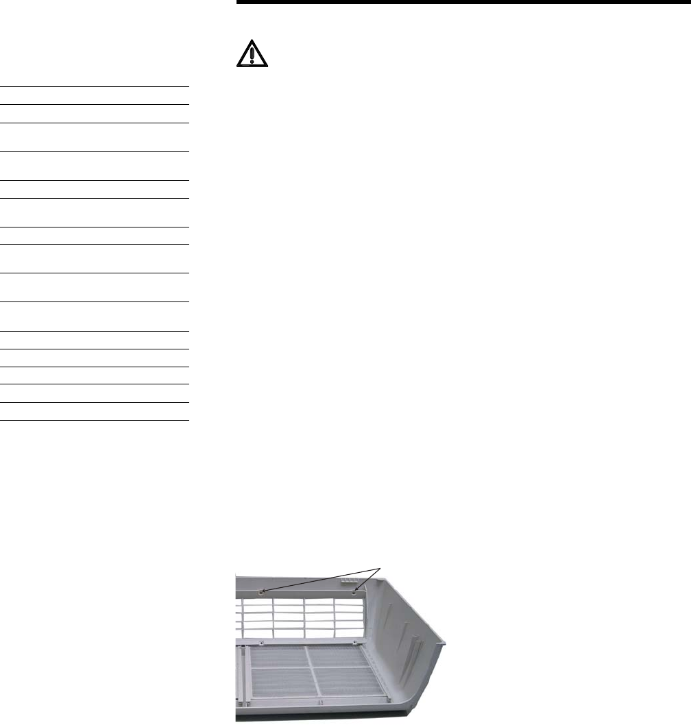
Air Discharge Grille
The discharge grille can be adjusted
to expel air at either a 15° or 40° (40°
default) angle. Figure 18.
To change the discharge air airflow
angle:
1. Remove the front cabinet.
2. Position the front cabinet so that
the backside is accessible.
3. Remove the four screws which
secure the discharge air grille to
the cabinet front with a phillips-
head screwdriver. See Figure 31.
4. Rotate the grille 180° end-for-
end.
5. Reinstall the screws securing the
discharge air grille to the cabinet
front. Reinstall the cabinet front
on the unit.
Figure 18. Discharge air grille
Screws