


PTAC-SVX01C-EN 37
Maintenance
Resistance Test
1. With no power, remove the leads
from the compressor terminals.
2. Touch the leads of an ohmmeter
to terminals C-S, start windings
and C-R, run winding.
If either winding does not test
continuous, replace the compressor.
Testing capacitance
capacitance (MFD) =
2650 X amperage
voltage
Note: Replace the capacitor if the
value obtained is not within
10% of the rating printed on
the capacitor.
Ground Test
WARNING
Live Electrical Components!
During installation, testing, servicing
and troubleshooting of this product,
it may be necessary to work with live
electrical components. Have a
qualified licensed electrician or other
individual who has been properly
trained in handling live electrical
components perform these tasks.
Failure to follow all electrical safety
precautions when exposed to live
electrical components could result in
death or serious injury.
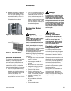
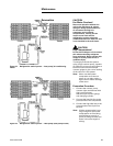
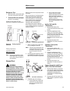
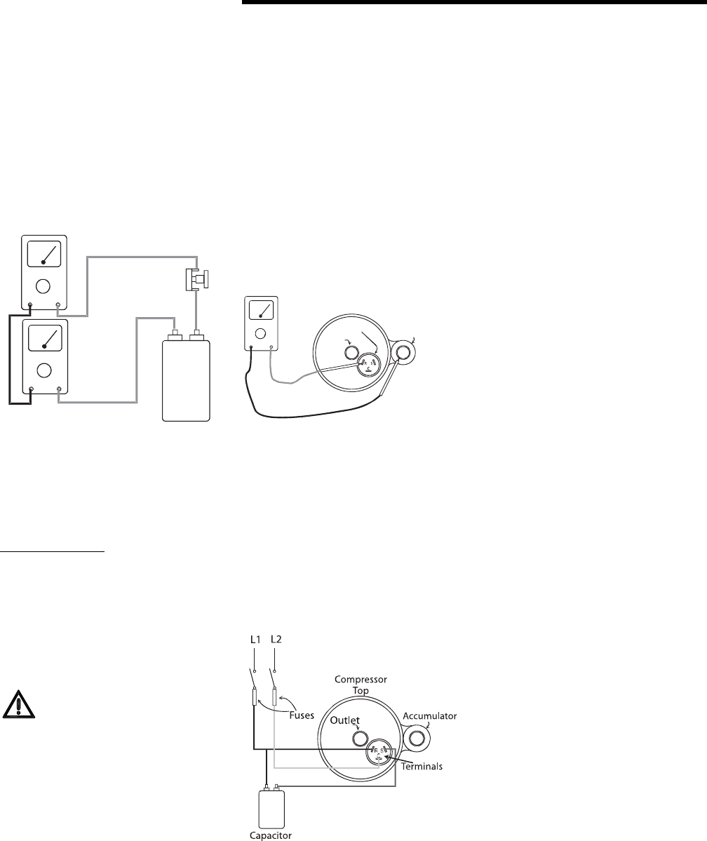
Figure 25. Testing capacitor
resistance
15 amp
fuse
Voltmeter
Ammeter
Capacitor
With no power and compressor leads
removed:
Set an ohmmeter on its highest scale.
Touch one lead to the compressor
body (clean point of contact, as a
good connection is a must) and the
other probe to each compressor
terminal in turn. If a reading is
obtained, then compressor is
grounded and must be replaced.
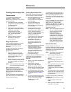
If the voltage, capacitor, overload and
motor windings test fail to show the
cause for failure:
1. With no power, wire a test cord
to line voltage (Line & N).
Note: The wire size of the test cord
must equal the line size, and
the fuses in the test line must
be of the proper size and
type.
2. Connect a good capacitor of the
right MFD and voltage rating into
the circuit as shown in Figure 40.
3. Carefully apply line voltage.
a. If the compressor starts and
continues run, the cause for
failure is somewhere else in
the system.
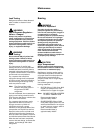
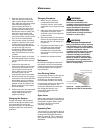
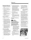
Figure 26. Compressor ground test
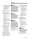
Figure 27. Test cord connections
Ohmeter
Compressor
top
Outlet
Terminals
Accumulator
b. If the motor fails to start -
replace. Since all single
phase compressors are of the
permanent split capacitor
design the high and low side
pressure must be
approximately equal or the
low torque compressor may
not start.
Indoor Coil and Air
Thermistors
1. Remove the Indoor Coil
Thermistor leads from the circuit
board.
2. Check the resistance of the
Indoor Coil Thermistor against
the table on the next page. The
leads of the ohm meter will need
to contact the ends of the
thermistors that connect to the
board.
3. Replace the Indoor Coil
Thermistor if it does not test as
above.
Outdoor Coil and Air
Thermistors
1. Remove the outdoor coil
thermistor leads from the circuit
board.
2. Check the resistance of the
outdoor coil thermistor against
the table on the next page. The
leads of the ohm meter will need
to contact the ends of the
thermistors that connect to the
board.
3. Replace the outdoor coil
thermistor if it does not test as
above.
Heater Assembly with Power
OFF to the Unit and Heater
1. Remove the heaters in question
and visually inspect the element
for broken condition. Refer to the
disassembly procedures for
information on disassembling
the heater.
2. Test the thermal fuse (one time
fuse). If open, replace the heater
assembly.